VMU Tests on A380
Source: Airbus Safety First URL: https://safetyfirst.airbus.com/vmu-tests-on-a380/ Published: 2011-07-14 Category: Archive PDF: Original PDF
The Airbus Safety Magazine
Claude LELAIE
Section titled “Claude LELAIE”Experimental Test Pilot
Introduction
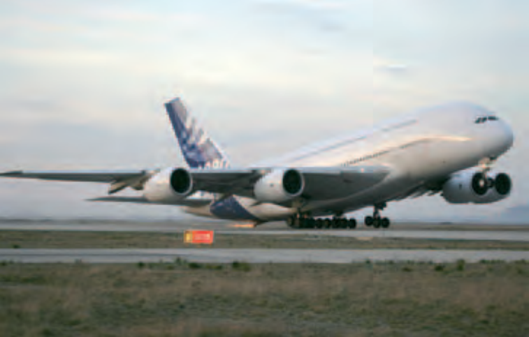
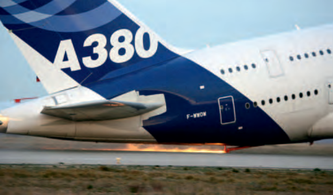
Section titled “Introduction”Almost all pilots have seen astonishing pictures of a test aircraft taking off with the tail scraping the runway with a lot of sparks coming from the rear fuselage during the testing for development and certification. The truth is that a specific tail bumper is added to protect the tail from any damage! But why do we need to do that?
definition of the VMu
Section titled “definition of the VMu”This test allows to determine speeds which are called VMU (Velocity Minimum Unstick). A given VMU is a function of weight, thrust, altitude, and CG. The aircraft actually gets airborne in a similar manner to a Piper J3 (even if not the standard procedure!), with a simultaneous lift-off of the main gears and the “tail wheel”, which is replaced by the tail bumper on the A380. There is no way to get airborne at a lower speed and this is the reason for the denomination.
We need to know the VMU because the computed take off speeds incorporate some margin above VMU, just as they also do for VS (Stall speed), VMCG (Minimum control speed on the ground) and VMCA (Minimum control speed in the air). These “V” speeds therefore form the basic building blocks of take-off performance.
On the A380, there was not only a need to establish the VMU for computation of the take off performance, but it was also necessary to perform some tests at the very
slats / flaps positions: 1+F, 2 and 3. Configuration 3 gives more lift and therefore allows the take-off at a lower speed with a reduced runway length. Alternatively, the minimum deflection, 1+F, gives a lower drag and a better rate of climb with one engine out. It is well adapted to the situation where there are obstacles far away, however, the take-off distance is increased. Configuration 2 is used to cover intermediate situations.
beginning of the development for the optimisation of the take-off aerodynamic configuration. This was done in the first three months of the development.
Optimization of Take-Off Performance
Section titled “Optimization of Take-Off Performance”The optimization of take-off performance is complex. Firstly, the aircraft must be able to get airborne safely, even in the case of failure of one engine. It may also have to overfly obstacles, close or far from the runway end, with sufficient margin, still with an engine failed. The optimization has to be performed for all weights, altitudes and temperatures and obviously some compromises have to be made, as no aircraft can be perfect for all conditions. On all Airbus FBW aircraft, the crew has the choice between three take-off
For the optimisation phase, we were able to “play” with slats and flaps deflection and with the size of the strake on the engines nacelle, and we had initially to compare two characteristics: stall speeds and rate of climb with one engine out.
The first stalls were performed on flight 3 with more being carried out in the following days. It allowed us to make a first choice among the configurations to be retained. Globally, the results were very good, even better than expected. The
Safety
stalls with a reduced slat deflection were not so satisfactory as it was possible to generate too much sideslip. With the initial position the stall characteristics were excellent. Easy choice!
Without strakes, the stall appeared earlier, with a definite loss of lift. Obviously strakes were needed. We tried several shapes of strake, some with a larger surface, without clear improvement, so we came back to those that had been fitted initially.
The measurements of the rate of climb with one engine out started the first month of flight tests (flights 9 to 12). Again the target was to check that, in all configurations, the performance was in line with the expectations, which proved to be the case.
Finally, for the flaps, we had to make a choice for the configuration 3 for take-off. When coming out of the assembly line, the initially planned deflection was 22°, but in the mean time the aerodynamicists
have found that 26° or 29° would be better. However, after the stalls and the rate of climb measurements, we were still not sure which setting was the best. Therefore we had to perform the VMU tests for a final assessment.
The difficulties of the VMu Tests
Section titled “The difficulties of the VMu Tests”Among all development and certification tests, VMU are probably among the most spectacular for observers, with the small “firework” below the tail just before lift-off. For crew members, they are also one of the most stressful, as the risk of damage to the aircraft is rather high. Few pilots can say that they have performed VMU tests on several programs without damaging anything!
In the case of the A380, some structural reinforcements were made during the installation of the tail bumper so that it could sustain a force up to 160 tons (we reached 100 tons during our tests). Because
the rearmost part of the plane was made of carbon, the bumper was installed slightly further forward in a metallic section. This had adverse consequences, as the protection of rear fuselage was not as good as if it had been mounted in an ideal position. It left a slight risk of contact after take-off behind the bumper. To cover this case, metallic protection was also installed over the carbon in the lower area of the aft fuselage.
There are several difficulties in carrying out VMU tests. The first one is to perform a soft touch down of the tail bumper, as the structure is not designed for a strong impact. This is even more difficult with high thrust and strong acceleration, as there is sometimes not more than one second between touch down of the bumper and lift-off. This particular test, when performed, is done at the end of the sequence, when the crew is well trained and practised in the technique.
For tests with a very low thrust setting, the rate of climb may be very small, and the aircraft could be fly-
The Airbus Safety Magazine
ing rather low for a long time after getting airborne. It is also possible that the aircraft can be “caught up” in ground effect where it maintains flight in a kind of “air cushion”, being unable to climb further. In this situation, there is no other solution than to perform a Go Around.
But the key issue is the fact that the regulations request that the pitch attitude must not be decreased below the value at lift-off. To perform a successful test, the pilot generally increases it slightly. However, the margin is only around 1° to 1.5° of additional pitch before touching with the tail, behind the tail bumper. This is the most frequent cause of damage, depending on individual aircraft flying characteristics. There is the challenge!
We need perfect weather conditions, with no turbulence and wind less than 5 kts, to insure the precision of the measurements. Another good reason is that we are flying close to the limits and we must not be destabilized by turbulence.
For these tests, all the audio warnings are “killed” by the crew prior to the test, otherwise the crew receive a stream of continuous warnings: “Thrust not set”, then “Stall, stall” and possibly some others. We must be able to work in a quiet environment.
The Flight Test Technique
Section titled “The Flight Test Technique”The flying technique, as developed by Airbus, is really specific to this type of test and airlines pilots will surely find that rather strange.
The left hand seat pilot is responsible for flying the pitch. His seat is in the lowest position as he does not need to see the runway. He adjusts the attitude using the horizon of the PFD, performing a smooth touch-down of the tail bumper, keeping the tail on the ground until lift-off and maintaining the pitch attitude after take-off until out of the ground effect (one wing span) or 400 ft.
The right hand seat pilot has his seat in the upper position to be able to see the runway even with a high pitch attitude. On the ground, he maintains the aircraft on the runway. When in flight, he keeps the roll close to zero using very small inputs on the rudder (induced roll), and not with ailerons and spoilers to avoid a drag increase. Finally, he is responsible for safety, which means that he can take over anytime, typically if the aircraft is not climbing in ground effect.
The Test Flight Engineer on the flight deck is in charge of setting very precisely the thrust, which is important when we are performing tests at very low ratio thrust over weight.
In the cabin, in front of all their screens, two Flight Test Engineers are monitoring the test, and thanks to the traces, they validate it (or not!).
Now, who is really the Captain? Is it the guy who can damage the aircraft while flying the pitch or the other one in charge of the safety? We have never really decided, but what is important is that the success is coming from a close team work as always in flight tests.
The Tests on A380
Section titled “The Tests on A380”As explained previously, the first tests had to be performed rather early in the program in order to optimize the configuration 3. We began on July 13th 2005 at Istres Air Force Base (South of France) where there is a 5 km runway and no houses or other obstacles on the runway axis for several kilometres. It was flight 41 and the first takeoff weight was 526 tons (followed obviously later by an overweight landing). Unfortunately, due to traffic then weather conditions we had to stop after only four tests.
During the first test, I was surprised by the reactions of the airplane,
which was different from the simulator, and the metallic part behind the tail bumper touched the runway. The damage was minor and we were able to continue the tests, taking into account the lessons learned from the first one!
The following day, July 14th, was the French National Day. So apart from two KC145 taking off for the parade on the Champs Elysées, there was no traffic and we were able to progress quickly. We exchanged seats between the two pilots. In the mean time, we found a method of changing the protection under the tail bumper without shutting down the engines. This saved time so that eventually seven successful tests were performed, mainly with the two possible settings for configuration 3.
The final result was the choice of a deflection of 26° for configuration 3, but with only a very small difference from the 29° setting. We planned initially four months to optimize the aerodynamic configuration, but all the characteristics were really excellent and everything was completed in less than three months.
Later in the development campaign, some more VMU had to be performed for the take-off performance computations. These were done on March 25th and 26th 2006. Eleven more tests were done in total, including those at very low thrust, down to 48 % of maximum thrust at 440 tons. For this last test we were still at 200 ft about 4 NM from brakes release, when finally we were able to climb out of ground effect!
A total of 22 VMU tests were executed including both development and certification.
来源: Airbus Safety First 网址: https://safetyfirst.airbus.com/vmu-tests-on-a380/ 发布日期: 2011-07-14 类别: 档案 PDF: 原始PDF
空客安全杂志
Claude LELAIE
Section titled “Claude LELAIE”试飞员
几乎所有飞行员都曾见过令人惊叹的画面:试验飞机起飞时,尾部在跑道上摩擦,后机身上火花四溅——这是在研发和认证试验期间拍到的画面。实际上,飞机会加装一个专用的尾翼保险杠来保护尾部免受损坏!但我们为什么要这样做呢?
VMU的定义
Section titled “VMU的定义”这项试验用于确定被称为VMU(最小离地速度)的速度。某一VMU值是重量、推力、高度和重心(CG)的函数。飞机实际上以类似于Piper J3的方式起飞(即使这不是标准程序!),主起落架和“尾轮”同时离地,在A380上“尾轮”被尾翼保险杠取代。不可能以更低的速度起飞,这就是VMU命名的原因。
我们需要了解VMU,因为计算的起飞速度会加入高于VMU的安全裕度,就像对VS(失速速度)、VMCG(地面最小控制速度)和VMCA(空中最小控制速度)所做的那样。因此,这些“V”速度构成了起飞性能的基本组成部分。
对于A380而言,不仅需要建立VMU用于计算起飞性能,还需要在研发初期进行某些试验,以优化起飞气动构型。这项工作在研发的前三个月内完成。
起飞性能优化
Section titled “起飞性能优化”起飞性能优化是一个复杂的过程。首先,飞机必须能够安全起飞,即使在单发失效的情况下。它还可能需要在仍有发动机失效的情况下,以足够的裕度飞越距跑道端近或远的障碍物。必须对所有重量、高度和温度进行优化,很明显需要进行一些权衡,因为没有飞机能在所有条件下都表现完美。在所有空客电传飞控飞机上,机组可以在三种起飞缝翼/襟翼位置之间进行选择:1+F、2和3。构型3提供更大的升力,因此可以以更低的速度起飞,减少跑道长度。相反,最小偏度1+F提供更低的阻力,在单发失效时具有更好的爬升率。它非常适合远处有障碍物的情况,但起飞距离会增加。构型2用于覆盖中间情况。
对于优化阶段,我们可以调节缝翼和襟翼偏度以及发动机短舱上整流罩的尺寸,初始阶段需要比较两个特性:失速速度和单发失效时的爬升率。
首次失速试验在第三次飞行中进行,随后几天又进行了更多试验。这使得我们能够在待保留的构型中做出初步选择。总体而言,结果非常好,甚至超出预期。采用减小缝翼偏度的失速试验不太令人满意,因为可能会产生过大的侧滑。使用初始位置时,失速特性非常出色。轻而易举的选择!
没有整流罩时,失速出现得更早,升力明显损失。显然需要整流罩。我们尝试了几种形状的整流罩,有些表面积更大,但没有明显改善,因此又回到了最初安装的那些。
安全
单发失效时的爬升率测量在飞行试验的第一个月(第九至第十二次飞行)开始。同样,目标是验证在所有构型下性能是否符合预期,事实证明了这一点。
最后,对于襟翼,我们必须在构型3中选择一个用于起飞。在总装下线时,初步计划的偏度为22°,但在此期间气动专家发现26°或29°会更好。然而,在进行失速和爬升率测量后,我们仍然不确定哪个设置最佳。因此,我们必须进行VMU试验以进行最终评估。
VMu 测试的难点
Section titled “VMu 测试的难点”在所有研发和取证试飞中,VMU 可能是对观察者来说最引人注目的项目之一,因为在离地前,尾部下方的”小烟花”令人印象深刻。对于机组人员来说,这也是最具压力的项目之一,因为对飞机造成损坏的风险相当高。很少有飞行员敢说自己曾在多个项目上完成 VMU 试飞而没有任何损坏!
在 A380 的案例中,尾减震器的结构加固在安装过程中完成,使其能够承受高达 160 吨的力(我们在测试中达到了 100 吨)。由于飞机的最后部分是碳纤维材质,减震器被安装在稍靠前的金属段上。这产生了不利后果,因为后机身段的保护不如安装在理想位置时那么好。减震器后方存在轻微的接触风险。为覆盖这种情况,下后机身的碳纤维区域也安装了金属保护。
进行 VMU 测试有几个困难。第一个是使尾减震器轻柔触地,因为其结构并非为承受强烈冲击而设计。在高推力和强加速的情况下更是如此,因为减震器触地和离地之间的时间往往不超过一秒。这项特殊测试安排在序列的末尾进行,此时机组人员已经过充分训练并熟练掌握了该技术。
对于极低推力设置的测试,上升率可能非常小,飞机在离地后可能会在很低的高度飞行很长时间。还有可能出现飞机被”困”在地面效应中的情况,即飞机保持在一种”气垫”状态飞行,无法进一步上升。在这种情况下,唯一的选择是执行复飞。
但关键问题是,法规要求俯仰姿态不得低于离地时的值。为了成功完成测试,飞行员通常会略微增加俯仰姿态。然而裕度只有大约 1° 到 1.5° 的额外俯仰余量,否则就会在减震器后方触地。这是造成损坏最常见的原因,取决于个别飞机的飞行特性。这就是挑战所在!
我们需要完美的天气条件,无颠簸且风速小于 5 节,以确保测量的精度。另一个重要原因是,我们正在接近极限飞行,绝不能被颠簸而失去稳定性。
在这些测试之前,机组人员会关闭所有音频警告,否则机组将收到连续不断的警告流:“推力未设置”,然后是”失速,失速”,可能还有其他警告。我们必须在安静的环境中工作。
飞行测试技术
Section titled “飞行测试技术”空客开发的飞行技术与这种类型的测试真正密切相关,航空公司的飞行员肯定会觉得相当奇怪。
左侧座位飞行员负责控制俯仰。他的座位处于最低位置,因为他不需要看到跑道。他使用 PFD 的水平姿态作为参考,调整姿态,使尾减震器轻柔触地,在离地前保持尾部和地面接触,并在离地后保持俯仰姿态,直到脱离地面效应(一个翼展)或达到 400 英尺。
右侧座位飞行员的座位处于最高位置,以便在很高的俯仰姿态下仍能看到跑道。在地面上,他保持飞机在跑道上。在飞行中,他使用非常小的方向舵输入(诱发的滚转)保持坡度接近零,而不是使用副翼和扰流板,以避免阻力增加。最后,他负责安全,这意味着他可以随时接管,通常是在飞机在地面效应中无法上升的情况下。
驾驶舱内的测试飞行工程师负责精确设定推力,这在执行极低推重比测试时尤为重要。
在客舱中,两名飞行测试工程师坐在所有屏幕前监控测试,他们通过轨迹曲线来验证测试结果(或者不通过!)。
那么,谁才是真正的机长?是那个在控制俯仰时可能损坏飞机的人,还是负责安全的那个人?我们从未真正定论,但重要的是,成功始终来自紧密的团队协作,这在飞行测试中始终如此。
A380 上的测试
Section titled “A380 上的测试”如前所述,由于需要在项目早期优化构型 3,第一次测试不得不提前进行。2005 年 7 月 13 日,我们在法国南部的伊斯特尔空军基地开始试验,那里有一条 5 公里的跑道,且在跑道延长线上数公里范围内没有房屋或其他障碍物。这是第 41 次飞行,首次起飞重量为 526 吨(随后显然进行了超重着陆)。遗憾的是,由于空中交通管制和天气条件的原因,我们在完成四次测试后不得不中止。
在第一次测试中,我对飞机的反应感到惊讶,这与模拟机上的表现不同,尾翼保险杠后面的金属部件触碰了跑道。损坏很小,我们能够继续测试,同时汲取了第一次试验的经验教训!
第二天,7 月 14 日,是法国国庆日。因此除了两架 KC145 为香榭丽舍大街阅兵式起飞外,没有其他空中交通,我们得以快速推进测试。两名飞行员交换了座位。与此同时,我们找到了一种方法,可以在不关闭发动机的情况下更换尾翼保险杠下方的保护装置。这节省了时间,最终成功完成了七次测试,主要使用构型 3 的两种可能设置。
最终结果是选择 26° 的偏转角用于构型 3,但与 29° 设置的差异非常小。我们最初计划用四个月时间来优化气动构型,但所有特性实际上都非常出色,全部工作在不到三个月内完成。
在随后的研发试飞阶段,还需要进行一些 VMU 测试以计算起飞性能。这些测试于 2006 年 3 月 25 日和 26 日进行。共完成了 11 次额外测试,包括使用非常低推力的测试,低至最大推力的 48%,在 440 吨重量下进行。在最后一次测试中,当我们终于能够脱离地面效应时,离地面约 200 英尺,距离松刹车点约 4 海里!
研发和取证阶段共计完成了 22 次 VMU 测试。