Engine Thrust Management - Thrust Setting at Takeoff
Source: Airbus Safety First URL: https://safetyfirst.airbus.com/engine-thrust-management-thrust-setting-at-takeoff/ Published: 2018-12-11 Category: Flight Ops, asymmetrical thrust, differential thrust, lateral runway excursion, runway, runway excursion, takeoff PDF: Original PDF
PROCEDURES
Section titled “PROCEDURES”Engine Thrust Management - Thrust Setting at Takeoff
The FCOM Standard Operating Procedures (SOP) provide specific guidance to flight crews for thrust application at takeoff. This article explains why 2-step thrust application is required at takeoff and why some extra steps should be taken in tailwind or significant crosswind conditions. It also provides recommendations to ensure optimum lateral control of the aircraft during takeoff roll and how to react if an asymmetric event is experienced at low speed.
Safety first #27 | December 2018 002

ANALYSIS OF AN EVENT
Section titled “ANALYSIS OF AN EVENT”Event Description
Section titled “Event Description”An A320 equipped with IAE engines was lined up for a static takeoff using Flex Thrust. It was 10:40pm local time, the runway was dry, the wind negligible and the outside air temperature had reached 33°C. There was a slight difference in the position of left and right thrust levers when the aircraft lined up on the runway that resulted in the following Engine Pressure Ratios (EPR) and N2 values:
The Pilot Flying (PF) then moved both thrust levers forward and paused for around 3 seconds near to the CLB detent where, the EPR and N2 increased to the the following values:
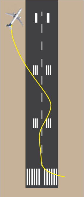
Eventually, the PF released the brakes and moved the thrust levers forward to the FLX detent. Engine 2 accelerated more rapidly than engine 1 and the resulting thrust asymmetry caused the aircraft to veer to the left. The PF tried to recover the trajectory by applying right rudder input and retarding the thrust levers to reduce thrust on both engines. Consequently, this caused the aircraft to sharply veer to the right. The PF applied differential thrust combined with left rudder pedals and tiller inputs. This caused the aircraft to veer sharply to its left while continuing to accelerate. The PF reacted again to apply full right rudder input combined with asymmetric braking and applied maximum thrust reversers in an attempt to stop the aircraft. The aircraft eventually came to rest to the left of the runway at 300 meters from the threshold (fig.1). During this event, the ground speed did not exceed 31 kt.
Event Analysis
Section titled “Event Analysis”The root cause of this event was the initial difficulty to control the aircraft laterally due to the rapid assymmetric thrust increase at low speed. We will analyse this phenomenon in the following paragraphs and explain how the pilots can ensure a symmetric thrust increases to ease the lateral control of the aircraft in the early takeoff roll.
(fig.1)
Section titled “(fig.1)”View from above of the aircraft trajectory
PROCEDURES
Section titled “PROCEDURES”Why could aircraft engines accelerate asymmetrically at takeoff?
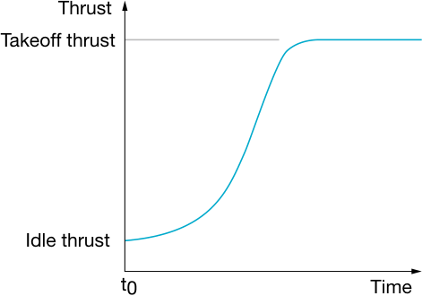
Section titled “Why could aircraft engines accelerate asymmetrically at takeoff?”On all jet engines, but particularly on high bypass ratio engines, the engine acceleration profile is not linear (fig.2). It follows the engine control law that is defined to optimize the acceleration in a way that the risk of engine stall is reduced. It also takes into account the influence of the position of the engine installed on the aircraft and the effect on the airflow at the engine’s inlet due to its proximity to the ground and the surrounding aircraft structure.
(fig.2) Typical engine acceleration profile.
Similarly, the idle thrust can slightly differ from one engine to the other, moving the acceleration profile to the left on the graph (fig.4).
Thrust Takeoff thrust Idle thrust
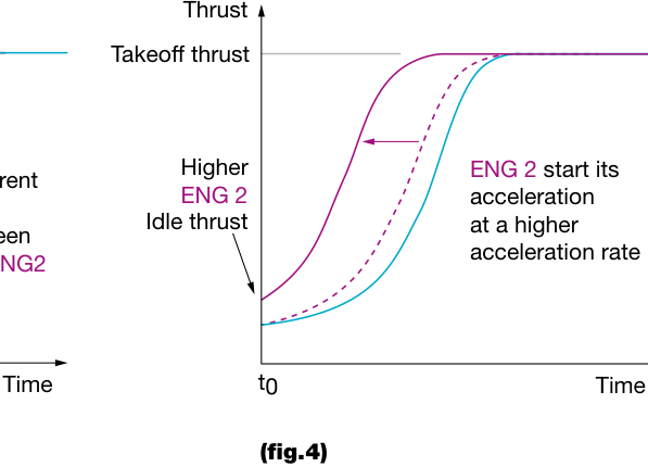
Difference between engines’ idle thrust.
Safety first #27 | December 2018 004
Taking into consideration both of these parameters, if the flight crew applies the takeoff thrust directly from idle thrust, without doing any stabilization step, the difference in engine acceleration performance could cause a strong asymmetric thrust condition (fig.5) that could be difficult to counteract with nose wheel steering only, due to limited effectivity of the rudder at low speed.
Direct takeoff thrust application with no thrust stabilization step potentially creates a strong thrust asymmetry that may be difficult to counteract.
ENSURING A SYMMETRIC THRUST INCREASE AT TAKEOFF
Section titled “ENSURING A SYMMETRIC THRUST INCREASE AT TAKEOFF”FCOM Standard Operating Procedure
Section titled “FCOM Standard Operating Procedure”To avoid this potential strong thrust asymmetry, the FCOM SOP for takeoff provides a procedure that requests pilots to apply takeoff thrust in two distinct steps (fig.6) with some additional guidance for certain aircraft operating in the case of tailwind or significant crosswind conditions.
A320 CFM or PW
Section titled “A320 CFM or PW”A320 IAE
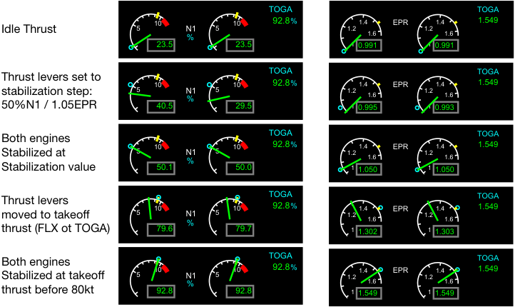
Example of the standard thrust setting procedure at takeoff for an A320 aircraft depending on the engine type.
PROCEDURES
Section titled “PROCEDURES”Why pilots should set thrust in two steps for takeoff?
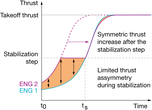
Section titled “Why pilots should set thrust in two steps for takeoff?”The stabilization step ensures that all engines reach a rotation speed value from where the increase of engine thrust will be almost identical to each other (fig.7). The N1/EPR/THR stabilization value is defined during flight test campaign for every engine type with collaboration from engine manufacturers.
(fig.7)
Section titled “(fig.7)”Using a stabilization step, the potential thrust asymmetry remains limited before the stabilization and both engines accelerate almost simultaneously from ts.
In some cases, differential thrust is used to line-up the aircraft on the runway. If the pilot commands takeoff power without first doing the engine thrust stabilization step, the resulting asymmetric thrust condition may be significant due the engines accelerating from an already very different rotation speed.
This is why a thrust stabilization step is important after using differential thrust to line-up the aircraft, to avoid causing a strong thrust asymmetry condition during the early stages of the takeoff roll.
Static takeoff or rolling takeoff?
Section titled “Static takeoff or rolling takeoff?”The FCOM describes procedures for a static takeoff, but a rolling takeoff is also permitted.
During static takeoff, the brakes are released at ts (fig.7) once all engines have reached the stabilization step value, therefore, the aircraft is not affected by any potential thrust asymmetry that can happen between t0 and ts.
If a rolling takeoff is performed, the pilot must also respect the stabilization step. The flight crew uses opposite rudder pedals inputs as the aircraft is rolling to counteract any thrust asymmetry experienced during the stabilization phase between t0 and ts. With the engines at a low rotation speed the potential thrust asymmetry remains limited up to the engine stabilization step value.
Safety first #27 | December 2018 006
Why an additional thrust setting is necessary in tailwind or significant crosswind conditions?
Section titled “Why an additional thrust setting is necessary in tailwind or significant crosswind conditions?”In tailwind and significant crosswind conditions, the airflow entering into the engines is modified (fig.8). Some perturbations may appear downstream of the leading edge of the engine inlet and potentially cause an engine stall if the perturbed airflow enters the core of the engine.
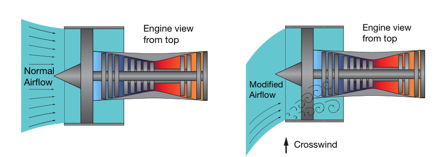
Typical airflow distortion affecting the fan and the engine core with associated airflow perturbations.
The FCOM thrust setting procedure in the case of tailwind or significant crosswind is in two steps:
-
Step one is to ensure engines increase their thrust symmetrically by using the stabilization step.
-
Step two is acceleration of the aircraft with the pilot progressively increasing thrust from the stabilization step value to reach takeoff thrust. As the aircraft accelerates the relative wind resulting from the forward momentum counters the disturbed airflow conditions caused by crosswind or tailwind, reducing the risk of engine stall and the risk of experiencing the associated thrust asymmetry.
For A330 and A380 equipped with Rolls Royce TRENT engines, the FCOM procedure does not request the pilot to apply progressive thrust application between the engine stabilization step and the takeoff thrust in case of tailwind or significant crosswind. The engine control logic automatically manages the engine thrust during the takeoff roll on these aircraft.
PROCEDURES
Section titled “PROCEDURES”Specificity of aircraft equipped with Rolls Royce and IAE engines
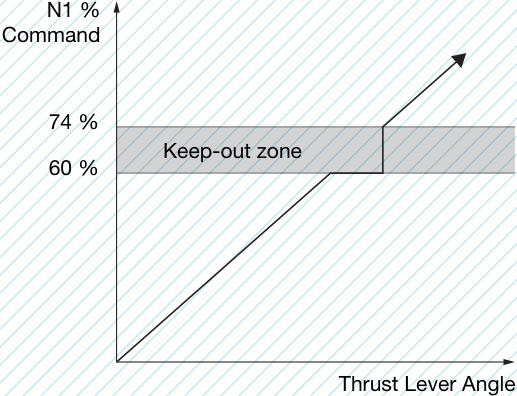
Section titled “Specificity of aircraft equipped with Rolls Royce and IAE engines”On aircraft equipped with Rolls Royce or IAE engines, a “keep-out zone” prevents stabilized engine operation in a specific N1/EPR range, when on ground below a certain speed, to prevent fan instability. During the progressive application of the takeoff thrust after the stabilization step, the flight crew should ensure that the levers are advanced continuously and simultaneously. Moving the thrust levers too slowly may lead to asymmetric engine acceleration if one thrust lever is moved outside of the keep-out zone before the other.
(fig.9)
Section titled “(fig.9)”Example of the keep-out zone on A320 aircraft equipped with IAE engines
In the case of an asymmetric thrust event at takeoff, the flight crew should reject the takeoff if the veering moment cannot be counteracted using nose wheel steering.
The technique described in the FCTM “engine failure at low speed” should be applied:
-
Immediately reduce all thrust levers to IDLE
-
Select all reversers
-
Use rudder pedals for directional control, supplemented by symmetrical or differential braking if needed
发动机推力管理 - 起飞推力设置
FCOM 标准操作程序(SOP)为飞行机组提供了起飞时推力施加的具体指导。本文解释了为什么起飞时需要分两步施加推力,以及在顺风或较大侧风条件下需要采取哪些额外措施。同时还提供了确保起飞滑跑期间飞机横向控制最优化的建议,以及如何在低空速遭遇非对称事件时作出反应。
Safety First #27 | 2018年12月 002
一架配备 IAE 发动机的 A320 飞机使用 Flex 推力进行静止起飞。当时是当地时间晚上10点40分,跑道干燥,风速可忽略不计,外部空气温度已达到33°C。飞机在跑道上就位时,左、右推力手柄位置存在轻微差异,导致以下发动机压力比(EPR)和 N2 值:
然后,副驾驶(PF)将两个推力手柄向前移动,并在 CLB 卡位附近暂停约3秒,在此期间 EPR 和 N2 值增加到以下数值:
最终,PF 松开刹车并将推力手柄向前推到 FLX 卡位。2号发动机比1号发动机加速更快,由此产生的推力不对称导致飞机向左偏转。PF 试图通过施加右方向舵输入并后移推力手柄以减少两台发动机的推力来修正轨迹。因此,飞机急剧向右偏转。PF 施加差分推力并结合左方向舵脚蹬和转向手轮输入。这导致飞机在继续加速的同时急剧向左偏转。PF 再次反应,施加最大右方向舵输入并结合非对称制动,同时使用最大反推力试图使飞机停下。飞机最终停在距离跑道入口300米处跑道的左侧 (图1)。在整个事件过程中,地速未超过31节。
此次事件的根本原因是低空速时发动机推力快速非对称增加,导致飞机横向控制困难。我们将在以下段落中分析这一现象,并解释飞行员如何确保推力对称增加,以简化起飞初期滑跑时的横向控制。
飞机轨迹俯视图
为什么飞机发动机在起飞时可能非对称加速?
Section titled “为什么飞机发动机在起飞时可能非对称加速?”在所有喷气发动机上,尤其是大涵道比发动机,发动机加速曲线并非线性的 (图2)。它遵循发动机控制规律,该规律定义了优化加速的方式以降低发动机喘振风险。同时还考虑了发动机安装在飞机上的位置以及因靠近地面和周围飞机结构而导致发动机进口气流受到影响。
(图2) 典型发动机加速曲线。
同样地,各发动机之间的慢车推力可能略有不同,使加速曲线在图上向左移动 (图4)。
推力 起飞推力 慢车推力
各发动机之间慢车推力的差异。
Safety First #27 | 2018年12月 004
综合考虑这两个参数,如果飞行机组从慢车推力直接施加起飞推力,而不进行任何稳定步骤,发动机加速性能的差异可能导致强烈的非对称推力状况 (图5),由于低空速时方向舵效能有限,仅用前轮转向可能难以抵消这种状况。
直接施加起飞推力而不进行推力稳定步骤,可能产生强烈的推力不对称,仅凭前轮转向可能难以抵消。
确保起飞时对称增加推力
Section titled “确保起飞时对称增加推力”FCOM 标准操作程序
Section titled “FCOM 标准操作程序”为避免潜在的强推力不对称,FCOM 起飞标准操作程序要求飞行员分两个明确的步骤施加起飞推力 (图 6),并在特定机型顺风或大侧风条件下提供额外指导。
A320 CFM 或 PW
Section titled “A320 CFM 或 PW”A320 IAE
根据发动机类型,A320 飞机标准推力设置程序示例。
为什么飞行员应在起飞时分两步设置推力?
Section titled “为什么飞行员应在起飞时分两步设置推力?”稳定化步骤确保所有发动机达到一个转速值,从该值开始发动机推力的增加几乎相同 (图 7)。N1/EPR/THR 稳定化值是在飞行试验期间与发动机厂商合作针对每种发动机类型定义的。
使用稳定化步骤后,潜在推力不对称在稳定化前保持有限,两台发动机几乎同时从 ts 开始加速。
在某些情况下,差动推力用于将飞机对正跑道。如果飞行员在未首先完成发动机推力稳定化步骤的情况下发出起飞功率指令,由于发动机从已存在较大差异的转速开始加速,产生的推力不对称状况可能非常显著。
这就是在使用差动推力对正后进行推力稳定化步骤如此重要的原因,可避免在起飞滑跑早期阶段产生强推力不对称。
静止起飞还是滑行起飞?
Section titled “静止起飞还是滑行起飞?”FCOM 描述了静止起飞的程序,但也允许滑行起飞。
在静止起飞时,一旦所有发动机达到稳定化步骤值,刹车在 ts(图 7) 处释放,因此飞机不受 t0 与 ts 之间可能发生的任何潜在推力不对称的影响。
如果执行滑行起飞,飞行员也必须遵守稳定化步骤。在飞机滑行过程中,机组使用方向舵踏板进行反向输入以抵消稳定化阶段 t0 至 ts 之间遇到的任何推力不对称。由于发动机处于低转速状态,在达到发动机稳定化步骤值之前,潜在推力不对称保持在有限范围内。
Safety first #27 | 2018 年 12 月 006
为什么在顺风或大侧风条件下需要额外的推力设置?
Section titled “为什么在顺风或大侧风条件下需要额外的推力设置?”在顺风和大侧风条件下,进入发动机的气流会发生变化 (图 8)。一些扰动可能出现在发动机进气道唇口下游,如果受扰气流进入发动机核心,可能导致发动机喘振。
影响风扇和发动机核心的典型气流畸变及相关气流扰动。
顺风或大侧风条件下的 FCOM 推力设置程序分为两个步骤:
-
第一步是通过使用稳定化步骤确保发动机对称增加推力。
-
第二步是飞机加速,飞行员将推力从稳定化步骤值逐渐增加至起飞推力。随着飞机加速,由前进动量产生的相对气流抵消侧风或顺风造成的气流扰动条件,降低发动机喘振风险及相关推力不对称风险。
对于配备罗尔斯·罗伊斯 TRENT 发动机的 A330 和 A380,FCOM 程序不要求飞行员在顺风或大侧风条件下于发动机稳定化步骤和起飞推力之间采用渐进式推力施加。发动机控制逻辑自动管理这些飞机在起飞滑跑期间的发动机推力。
配备罗尔斯·罗伊斯和 IAE 发动机的飞机特殊性
Section titled “配备罗尔斯·罗伊斯和 IAE 发动机的飞机特殊性”配备罗尔斯·罗伊斯或 IAE 发动机的飞机存在一个“禁入区”,在地面且低于特定速度时,阻止发动机在特定的 N1/EPR 范围内稳定运行,以防止风扇不稳定。在稳定化步骤后渐进施加起飞推力期间,机组应确保推力手柄连续且同时向前推动。如果一个推力手柄在另一个之前移出禁入区,移动推力手柄过慢可能导致不对称的发动机加速。
A320 飞机配备 IAE 发动机的禁入区示例
在起飞时发生不对称推力事件的情况下,如果偏航力矩无法通过前轮转向抵消,机组应中断起飞。
应采用 FCTM 中“低速发动机失效”描述的技术:
-
立即将所有推力手柄收至慢车
-
选择所有反推
-
使用方向舵踏板进行方向控制,必要时辅以对称或差动刹车