A320 Family/ Evolution of ground spoiler logic
Source: Airbus Safety First URL: https://safetyfirst.airbus.com/a320-family-evolution-of-ground-spoiler-logic/ Published: 2010-02-14 Magazine Issue: 2010-02 Category: Archive PDF: Original PDF
Stéphane BOISSENIN
Section titled “Stéphane BOISSENIN”Engineer, Handling Qualities Engineering
Elisabeth SALAVY
Section titled “Elisabeth SALAVY”Engineer, Flight Control Systems Engineering
A320 Family/ Evolution of ground spoiler logic
Section titled “A320 Family/ Evolution of ground spoiler logic”1. Introduction
Section titled “1. Introduction”Ground spoilers reduce the lift produced by the wings and hence transfer the weight of the aircraft to the landing gear, allowing a more effective wheel braking action.
Their non or untimely extension has been a factor in the following types of A320 Family events:
q The absence of spoiler extension contributed to increase the stopping distance during landing.
q The untimely spoiler extension contributed to a number of hard landings.
In both cases, the cause could be traced back to non arming of the ground spoilers and/or inappropriate thrust levers positions during the flare.
To reduce the frequency of these events, Airbus has modified the spoiler extension logic.
The new logic is now tolerant to inappropriate speed brake and/or thrust levers positions.
This modification applies to the complete as well as to the partial ground spoiler extension.
It was achieved by creating a new standard of Spoiler Elevator Computer (SEC), which is in charge of spoiler control, the SEC standard 120.
This article will describe:
Section titled “This article will describe:”q The current ground spoiler extension conditions.
q The identified causes of runway excursion and hard landings.
q How the new SEC standard will reduce the number of these occurrences.
2. Current ground spoiler extension conditions
Section titled “2. Current ground spoiler extension conditions”2.1. Full extension
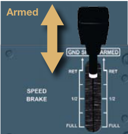
Section titled “2.1. Full extension”Depending on whether the ground spoilers have been armed or not, the following conditions must be met for their full automatic extension (as outlined in FCOM 1.27.10 p12):
-
q Ground spoilers armed (fig. 1) • Both main landing gears seen on ground.
-
Both thrust levers at or below Idle notch (fig. 2).
Safety
- q Ground spoilers not armed (fig. 3) • Both main landing gears seen on ground.
3.2. Hard landings
Section titled “3.2. Hard landings”Among hard landings, one specific category has been identified where by the hard landing occurred after a bounce. They fit to the following scenario (fig. 7) :
- Reverse is selected on at least one engine (the other thrust lever must be at or below Idle notch, fig. 4 ).
q e No engine throttle reduction (retard) during the flare p No ground spoiler extension.
2.2 Partial extension
Section titled “2.2 Partial extension”The Phased Lift Dumping function allows the ground spoilers to deploy with a reduced deflection and serves to accelerate the full spoiler extension when landing in crosswind conditions or on contaminated runways.
q r Bounce induced by a too high energy level and by the lack of lift destruction.
q t Engine throttle reduction performed during the bounce p Ground spoiler extension if the retard is performed within 3 seconds following the first touchdown.
The necessary conditions to trigger the partial ground spoiler extension, independently of the position of the ground spoiler lever are: q One main landing gear seen on ground.
q u Severe hard landing due to sudden loss of lift leading to a fall from a height of about 5ft to 15 ft.
q Reverse is selected on at least one engine (the other thrust lever must be at or below Idle notch).
It has been established that most of the hard landings occurring after a bounce are severe.
3. In-service events
Section titled “3. In-service events”The genesis of this flight control computer modification is coming from two types of events:
3.1. Longitudinal runway excursion
Section titled “3.1. Longitudinal runway excursion”Runway excursions resulted from the spoilers not extending during the landing.
This was traced to the following two causes:
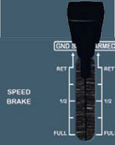
q The speed brake lever was in a non retracted position (fig. 5).
q One engine throttle was not in the area that authorized ground spoiler extension (fig. 6).
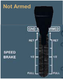
Figure 3
Figure 4
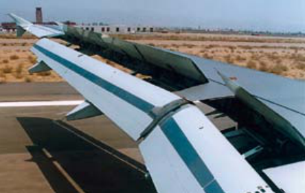
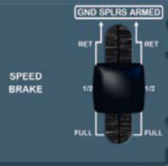
Figure 7
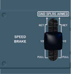
Figure 8 Expanded ground spoiler arming condition based on more tolerant speed brake lever position.
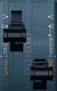
Figure 10 Expanded ground spoiler extension condition based on more tolerant thrust lever position
Figure 9
4. Expanded ground spoiler extension conditions
Section titled “4. Expanded ground spoiler extension conditions”4.1. General philosophy
Section titled “4.1. General philosophy”The Airbus philosophy regarding the ground spoiler activation logic is still based on the achievement of the following three conditions:
q Arming
-
q Ground detection
-
q Thrust lever position
The arming and thrust lever position conditions have been expanded to be more tolerant to inappropriate speed brake and thrust lever positions.
The ground detection condition has been expanded as well, albeit only for the partial ground spoiler extension, to address failures of ground detection sensors.
4.2. Changes introduced to limit runway excursions
Section titled “4.2. Changes introduced to limit runway excursions”The changes introduced by the new SEC 120 standard are highlighted in bold.
Complete ground spoiler extension conditions
Section titled “Complete ground spoiler extension conditions”q Ground spoilers armed or speed brake lever in non retracted position (fig. 8).
- Both main landing gears seen on ground.
• Both thrust levers at or below Idle notch or Reverse is selected on at least one engine (the other thrust lever must be below the Maximum Continuous - MCT- notch).
-
q Ground spoilers not armed (fig. 9) • Both main landing gears seen on ground.
-
Reverse is selected on at least one engine ( the other thrust lever must be below the Maximum Continuous - MCT - notch, fig. 10 ).
Partial ground spoiler extension conditions
Section titled “Partial ground spoiler extension conditions”The partial ground spoiler extension conditions have been expanded to mirror the full spoiler extension conditions.
-
q Ground spoilers armed or speed brake lever in non retracted position • One main landing gear seen on ground.
-
Both thrust levers at or below
-
Idle notch.
q Ground spoilers not armed
Section titled “q Ground spoilers not armed”-
One main landing gear seen on ground.
-
Reverse is selected on at least one engine ( the other thrust lever must be below the Maximum Continuous - MCT - notch ).
All combinations that would trigger the full ground spoiler extension hide the partial ground spoiler extension.
4.3. Changes introduced to limit bounces at landing
Section titled “4.3. Changes introduced to limit bounces at landing”A new spoiler extension logic is proposed on the SEC 120 to minimize the magnitude of the bounce in the event of an inappropriate thrust lever position during the flare.
1
Figure 11
3
Safety
This logic provides some lift destruction through the partial extension of ground spoilers as soon as ground conditions are detected on both landing gears, as long as both thrust levers are at or below the Climb notch (ATHR).
5. Conclusion
Section titled “5. Conclusion”Runway excursion and hard landing events have prompted Airbus to develop a new standard of Spoiler Elevator Computer, the SEC 120.
Expansion of the ground spoiler New ground spoiler partial exten- extension conditions means that sion conditions: the spoilers will extend even q Ground spoilers armed. when the speed brake and/or q Both main landing gears seen thrust levers are in inappropriate positions, thereby improving the on ground. aircraft’s deceleration on q Both thrust levers at or below ground. the Climb notch (ATHR).
In addition, a new ground spoiler partial extension logic has been developed to limit bounces that may lead to hard landings.
Landing scenario with SEC 120 (fig. 11) :
q e No engine throttle reduction (retard) during the flare p No ground spoiler extension.
To summarize, the SEC standard 120 provides means to reduce:
q Runway excursions by enabling:
q r With the SEC 120 modification, the ground spoilers will extend partially at touchdown, as long as both engines levers are at or below the Climb notch (ATHR). Lift is decreased and the bounce is reduced or cancelled.
• Arming of the ground spoilers even when the speed brake lever is not retracted.
• Extension of the ground spoilers even with a thrust lever above the Idle position.
q Hard landings by minimizing:
q t As soon as the thrust lever conditions are fulfilled (for instance engine throttle reduction to Idle), the ground spoilers extend fully (if achieved within 3 seconds of the initial touchdown).
• The number and amplitude of bounces by triggering partial spoiler extension at touchdown even with both thrust levers in the ATHR position.
q u As the height of the bounce is significantly reduced, the vertical speed at the second touchdown is largely reduced as well.
| Computer hardware | Modifcation number | Service Bulletin number |
|---|
The SEC 120 will become production standard on A320 Family from MSN 4472 on.
Annexe
Section titled “Annexe”Hard landing effect following bounce is reduced by 50%.
Section titled “Hard landing effect following bounce is reduced by 50%.”The modification proposed to reduce bounce occurrences at landing has been validated using a back to back approach. A dozen of major hard landing occurrences following a bounce have been simulated with Airbus flight dynamics simulations tools with and without the partial ground spoiler extension at touchdown.
Without the partial spoiler extension at the first touchdown, the average vertical load factor at the second touchdown is about 3.2g. With the SEC 120 modification allowing partial ground spoiler extension on ground even with thrust levers on Climb (ATHR) notch, the average load factor at the second touchdown is reduced to about 1.7g.
Example of typical hard landing event
Section titled “Example of typical hard landing event”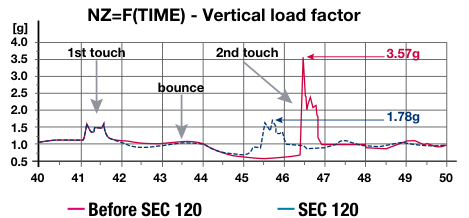
A statistical analysis has revealed that a significant bounce (Nz>1.6g) occurs in about 50% of the hard landing events. In about half of those cases (i.e. 25% of all hard landings), the second impact is harder than the first one.
More globally, the ground spoiler extension during a bounce has been identified as the root cause of the hard landing in 15% to 20% of the cases. Moreover, those events also represent 40% of the cases with costly issues (aircraft grounded, structural damages, landing gear changes …).
Safety
Stéphane BOISSENIN
Section titled “Stéphane BOISSENIN”工程师,飞控品质工程
Elisabeth SALAVY
Section titled “Elisabeth SALAVY”工程师,飞控系统工程
A320 系列/地面扰流板逻辑的演进
Section titled “A320 系列/地面扰流板逻辑的演进”地面扰流板可减少机翼产生的升力,从而将飞机重量转移至起落架,使机轮制动更加有效。
在以下类型的 A320 系列事件中,地面扰流板未伸出或伸出时机不当是因素之一:
q 地面扰流板未伸出导致着陆距离增加。
q 地面扰流板伸出时机不当导致多次硬着陆。
在这两种情况下,原因都可追溯到地面扰流板未预位和/或在拉平阶段油门杆位置不当。
为减少此类事件的发生,空客对扰流板伸出逻辑进行了修改。
新逻辑对不当的减速板和/或油门杆位置具有容错性。
该修改适用于全部和部分地面扰流板伸出。
通过创建新的扰流板升降舵计算机(Spoiler Elevator Computer,SEC)标准实现,该计算机负责扰流板控制,即 SEC 标准 120。
本文将描述:
Section titled “本文将描述:”q 当前地面扰流板伸出的条件。
q 跑道偏出和硬着陆的已识别原因。
q 新的 SEC 标准将如何减少此类事件的发生。
2. 当前地面扰流板伸出条件
Section titled “2. 当前地面扰流板伸出条件”2.1. 完全伸出
Section titled “2.1. 完全伸出”根据地面扰流板是否已预位,扰流板的完全自动伸出需要满足以下条件(如 FCOM 1.27.10 p12 所述):
-
q 地面扰流板已预位 (图 1) • 两个主起落架均感知到地面。
-
两个油门杆处于或低于慢车卡位 (图 2)。
安全
- q 地面扰流板未预位 (图 3) • 两个主起落架均感知到地面。
3.2. 硬着陆
Section titled “3.2. 硬着陆”在硬着陆中,已识别出一种特定类别,即硬着陆发生在弹跳之后。其符合以下场景 (图 7):
- 至少一台发动机选择了反推(另一油门杆必须处于或低于慢车卡位,图 4)。
q e 拉平阶段未执行发动机油门减小(减速)p 地面扰流板未伸出。
q r 弹跳由能量水平过高和缺乏升力破坏引起。
q t 在弹跳过程中执行了发动机油门减小 p 地面扰流板伸出(若减速在首次接地后 3 秒内完成)。
触发部分地面扰流板伸出的必要条件,与地面扰流板手柄位置无关:
q 一个主起落架感知到地面。
q 一个主起落架感知到地面。
q 至少一台发动机选择了反推(另一油门杆必须处于或低于慢车卡位)。
已确认大多数弹跳后发生的硬着陆都是严重的。
3. 服役中的事件
Section titled “3. 服役中的事件”此次飞控计算机修改的起源来自两类事件:
3.1. 纵向跑道偏出
Section titled “3.1. 纵向跑道偏出”跑道偏出是由扰流板在着陆时未伸出所致。
原因可追溯到以下两点:
q 减速板手柄处于非收回位置 (图 5)。
q 一台发动机油门不在允许地面扰流板伸出的范围内 (图 6)。
图 3
图 4
图 7
图 8 基于对减速板手柄位置更具容错性的扩展地面扰流板预位条件。
图 10 基于对油门杆位置更具容错性的扩展地面扰流板伸出条件
图 9
4. 扩展的地面扰流板伸出条件
Section titled “4. 扩展的地面扰流板伸出条件”4.1. 基本原理
Section titled “4.1. 基本原理”空客关于地面扰流板激活逻辑的基本原则仍然基于以下三个条件的达成:
-
预位
-
接地探测
-
推力手柄位置
预位条件和推力手柄位置条件已扩展,对不适当的减速板和推力手柄位置具有更高的容错度。
接地探测条件也同样进行了扩展,但仅限于部分地面扰流板伸出,以应对接地探测传感器故障。
4.2. 为减少跑道偏出而引入的更改
Section titled “4.2. 为减少跑道偏出而引入的更改”新 SEC 120 标准引入的更改以粗体突出显示。
全地面扰流板伸出条件
Section titled “全地面扰流板伸出条件”-
地面扰流板预位或 减速板手柄处于非收上位置(图 8)。
-
两个主起落架均探测到接地。
-
两个推力手柄在慢车卡位或低于慢车卡位,或者至少一台发动机选择了反推(另一个推力手柄必须低于最大连续推力 - MCT - 卡位)。
或
-
地面扰流板未预位(图 9)
-
两个主起落架均探测到接地。
-
至少一台发动机选择了反推(另一个推力手柄必须低于最大连续推力 - MCT - 卡位,图 10)。
部分地面扰流板伸出条件
Section titled “部分地面扰流板伸出条件”部分地面扰流板伸出条件已扩展,与全扰流板伸出条件保持一致。
-
地面扰流板预位或 减速板手柄处于非收上位置
-
一个主起落架探测到接地。
-
两个推力手柄在慢车卡位或低于慢车卡位。
或
-
地面扰流板未预位
-
一个主起落架探测到接地。
-
至少一台发动机选择了反推(另一个推力手柄必须低于最大连续推力 - MCT - 卡位)。
注意
所有触发全地面扰流板伸出的组合条件均会覆盖部分地面扰流板伸出。
4.3. 为减少着陆跳跃而引入的更改
Section titled “4.3. 为减少着陆跳跃而引入的更改”SEC 120 提出了一种新的扰流板伸出逻辑,以尽量减少在拉平阶段推力手柄位置不当时发生跳跃的幅度。
此逻辑提供了一定的升力消除效果,通过在两个起落架均探测到接地条件时立即部分伸出地面扰流板来实现,只要两个推力手柄在爬升卡位(ATHR)或低于爬升卡位。
跑道偏出和硬着陆事件促使空客开发了新一代扰流板升降计算机标准——SEC 120。
地面扰流板伸出条件的扩展意味着即使减速板和/或推力手柄处于不适当位置,扰流板也将伸出,从而改善了飞机在地面上的减速性能。
此外,还开发了一种新的地面扰流板部分伸出逻辑,以限制可能导致硬着陆的跳跃。
SEC 120 着陆场景(图 11):
- 拉平阶段无发动机油门收回到减速(RETARD)提醒 → 无地面扰流板伸出。
总之,SEC 120 标准提供了以下减少手段:
通过以下方式减少跑道偏出:
-
即使减速板手柄未收上,也可预位地面扰流板。
-
即使推力手柄高于慢车位置,地面扰流板也可伸出。
通过以下方式减少硬着陆:
-
通过在着陆触地时即使两个推力手柄处于爬升(ATHR)位置也触发部分扰流板伸出,减少跳跃的次数和幅度。
-
使用 SEC 120 改装后,只要两个发动机推力手柄在爬升卡位(ATHR)或低于爬升卡位,地面扰流板将在触地时部分伸出。升力减小,跳跃被减小或消除。
-
当推力手柄条件满足时(例如发动机油门收回至慢车),地面扰流板将完全伸出(如在首次触地后 3 秒内满足条件)。
-
由于跳跃高度显著减小,第二次触地时的垂直速度也大幅降低。
| 计算机硬件 | 改装编号 | 服务通告编号 |
|---|---|---|
SEC 120 将成为从 MSN 4472 起的 A320 系列飞机的生产标准。
跳跃后硬着陆的影响减少 50%。
Section titled “跳跃后硬着陆的影响减少 50%。”为减少着陆跳跃所提出的改装已通过回溯对比方法进行了验证。利用空客飞行动力学仿真工具,模拟了十余起主要跳跃后硬着陆事件,分别在有和无触地时部分地面扰流板伸出的情况下进行对比。
在不进行首次触地时部分扰流板伸出的情况下,第二次触地时的平均垂直载荷因子约为 3.2g。采用了 SEC 120 改装(允许推力手柄在爬升卡位(ATHR)时部分伸出地面扰流板)后,第二次触地时的平均载荷因子降低至约 1.7g。
典型硬着陆事件示例
Section titled “典型硬着陆事件示例”
统计数据分析表明,在硬着陆事件中,约 50% 会发生显著跳跃(N z >1.6g)。在这些案例中,约有一半(即所有硬着陆的 25%)的第二次撞击比第一次更重。
从更广的范围来看,在 15% 至 20% 的硬着陆案例中,跳跃期间的地面扰流板伸出被确定为硬着陆的根本原因。此外,这些事件也占高成本问题案例的 40%(飞机停飞、结构损坏、更换起落架等)。