Optimum use of weather radar
Source: Airbus Safety First URL: https://safetyfirst.airbus.com/optimum-use-of-weather-radar/ Published: 2016-07-29 Magazine Issue: 2016-07 Category: Flight Ops, autotiltgain, cloud, collins, convective, cumulonimbus, hail, hailstorm, honeywell, ice, lightning, multiscan, radar, rain, rdr-4000, rockwell, storm, strikes, thunderstorm, tilt, turbulence, weather radar, windshear PDF: Original PDF
In recent years, there have been a number of fl ights where passengers or crew suffered injuries due to severe turbulence. In some other instances, the aircraft structure was substantially damaged following a hailstorm encounter. Clearly adverse weather can pose a threat to the safe and comfortable completion of a fl ight, thus it needs to be detected and avoided in a timely manner.

DAVID MARCONNET
Section titled “DAVID MARCONNET”Flight Operations Support & Training Standards Safety Enhancement
CHRISTIAN NORDEN
Section titled “CHRISTIAN NORDEN”Director Flight Operations & Training Policy
LAURENT VIDAL
Section titled “LAURENT VIDAL”Surveillance Systems Manager

The airborne weather radar system is an essential tool for pilots to assess the intensity of convective weather ahead of the aircraft. In this respect, it enables the strategic and tactical planning of a safe flight trajectory.
Weather radar technology has evolved significantly in the last few years and a range of enhanced products is now available. If properly used, they permit pilots workload to be significantly reduced while substantially reducing encounters with adverse weather.
This article offers an overview of the existing weather radar technologies, and provides information and tips on how to tune the system and correctly interpret the available displays.
WEATHER RADAR PRINCIPLE AND OPERATION
Section titled “WEATHER RADAR PRINCIPLE AND OPERATION”The weather radar system installed on-board aircraft provides the pilot with the necessary information to avoid - not penetrate - adverse weather. To obtain the maximum benefit from the weather radar system requires
the crew to carefully optimize its use. This relies primarily on a good meteorological knowledge of weather phenomena, along with a good understanding of the available radar functions.
Prevention through anticipation is essential.
Flying in adverse weather: lessons learned
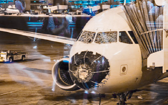
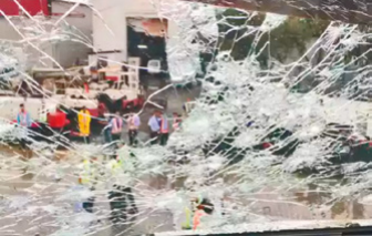
Section titled “Flying in adverse weather: lessons learned”The aviation industry experience shows that although aircraft are equipped with airborne weather radars, incursions into very active convective cells still occur, resulting in injuries or substantial
When it comes to understanding why aircraft fitted with technologically advanced weather radars can end up flying in such unfavorable weather patterns, we have to consider that getting the best out of technology onboard is just a part of the answer. A key element of adverse weather avoidance strategies
aircraft damage (fig.1).
These events have led us to wonder why such encounters happen, and clearly show that prevention through anticipation is essential.
is the active monitoring of the overall meteorological situation by the crew, in addition to the optimum use of the weather radar and correct understanding of the information displayed. We must not forget that weather radar is of help, but the crew overall assessment of the weather situation plays the central role.
(fig.1) Radome and windshield after hail encounter
Weather radar is of help, but the crew overall assessment of the weather situation plays the central role.
HOW IS A CUMULONIMBUS, OFTEN CALLED “THUNDERSTORM”, STRUCTURED?
Section titled “HOW IS A CUMULONIMBUS, OFTEN CALLED “THUNDERSTORM”, STRUCTURED?”Three common threats to aircraft are turbulence (which is caused when two masses of air collide at different speeds), hail and windshear. All three of these are by-products of thunderstorms.
Understanding how a cumulonimbus cloud is structured and evolves is key in dodging the associated weather disturbances.
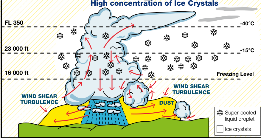
Turbulence associated with a cumulonimbus is not limited to inside the cloud. Therefore, when fl ying in an area where cumulonimbus clouds have developed,
it is necessary to apply recommendations for weather avoidance as summarized in this article.
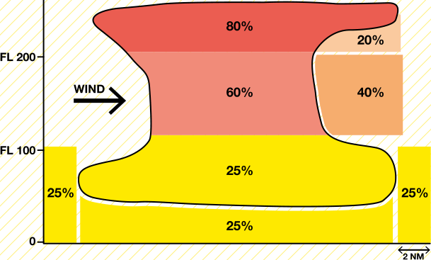
The presence of hail within a cumulonimbus varies with altitude and wind:
-
Below FL 100, hail is equally likely to be encountered under the storm, in the cloud or around it (up to 2 NM).
-
Between FL 100 and FL 200, approximately 60 percent of hail is encountered in the cumulonimbus and 40 percent is encountered outside the cloud, under the anvil.
-
Above FL 200, hail is most likely to be encountered inside the cloud.
When hail is encountered outside the cloud, usually the threat of hail is greater downwind of the cumulonimbus because moisture is
Risk of encountering hail relative to cumulonimbus cloud position
is less risk of hail in humid air than in dry air. In fact, moisture in the air behaves as a heat conductor, and helps to melt the hail.
driven upward within the cloud by strong drafts. It then freezes and is transformed into hail before being blown downwind. Paradoxically, there
Weather radar principle
Section titled “Weather radar principle”A knowledge of the radar principle is paramount in order to accurately
tune this system and interpret the weather radar display correctly.
Reflectivity
Section titled “Reflectivity”Weather detection is based on the reflectivity of water droplets (fig.2). The weather echo appears on the Navigation Display (ND) with a color scale that goes from red (high reflectivity) to green (low reflectivity).
The weather radar echo returns vary in intensity as a function of the droplet size, composition and quantity. For example, a water particle is five times more reflective than an ice particle of the same size.
of light rainfall, depicted in green in normal mode, is shown in magenta when there is high turbulence activity. The TURB function is on most weather radars only active within a range of 40 NM (Doppler measurement capability) and should only be used in wet turbulence.
Weather radar operation
Section titled “Weather radar operation”The flight crew uses four features to operate the radar:
has an essential influence on the optimum tilt setting.
-
Gain control: this adjusts the sensitivity of the receiver.
-
Antenna tilt: this is the angle between the centre of the beam and the horizon (fig.3).
-
Radar modes: weather (WX) or weather + turbulence (WX + T).
-
Range control of the ND: this
On the Airbus fleet, all weather radars have full capability to allow wet turbulence detection.
(fig.2) Weather radar principle
DID YOU KNOW
Section titled “DID YOU KNOW”Each type of weather radar has its own particularities. To get all the information on the characteristics, limitations and operational recommendations of each weather radar model, the user guide of the radar manufacturer needs to be studied.
(fig.3) Definition of the TILT
Weather radar limitations
Section titled “Weather radar limitations”Weather radar detection capability
Section titled “Weather radar detection capability”Refl ectivity is not directly proportional to the level of risk that may be encountered.
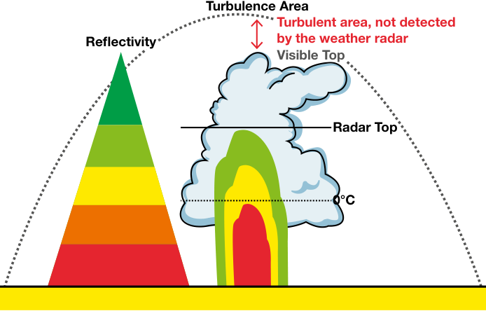
(fi g.4) Refl ective image of a cumulonimbus
One of the weather radar limitations is that it indicates only the presence of liquid water. The consequence is that a thunderstorm does not have the same refl ectivity over its altitude range because the quantity of liquid water in the atmosphere decreases with the altitude (fig.4). Yet, the convective cloud and associated threats may extend signifi cantly above the upper detection limit of the weather radar (called ‘radar top’). This means that refl ectivity is not directly proportional to the level of risk that may be encountered: a convective cloud may be dangerous, even if the radar echo is weak.
winds produce large scale uplifts of dry air. The resulting weather cells have much less refl ectivity than mid-latitude convective cells. However, turbulence in or above such clouds may have a higher intensity than indicated by the image on the weather radar display. On the other hand, air close to the sea can be very humid. In this case, thermal convection will produce clouds that are full of water: these clouds will have a high refl ectivity, but may not necessarily be a high threat.
Consequently, limitations of weather radars must be well understood and complemented by basic meteorological knowledge of the crew and, where possible, visual observation.
This is particularly true for equatorial overland regions where converging
The weather radar does not detect:
Section titled “The weather radar does not detect:”-
Rainfall - Ice crystals, dry hail * and snow - Wet hail and wet turbulence - Clear air turbulence - Windshear - Sandstorms (solid particles are almost transparent to the radar beam)
-
- Lightning *
-
The latest generations of weather radars offer hail and lightning prediction functions (see the following sections).
The beam attenuation phenomenon
Section titled “The beam attenuation phenomenon”Another limitation of the weather radar is called ‘shadowing’ or ‘attenuation’. The weather radar display depends on signal returns: the more intense the precipitation, the less distance the radar can see through. Therefore when the radar echo is unable to make the two way trip through heavy precipitation, a ‘shadowing’ effect occurs. The result is twofold. First, the size, shape
and intensity of that weather may not be accurately displayed to the pilot. What appears to be a thin or inexistent band of precipitation (fig.5) could in fact be the leading edge of a much larger area of precipitation. Secondly, any weather behind such strong shadowing cells will not be detected. This can result in unexpected weather unfolding only after the cell has been circumnavigated.
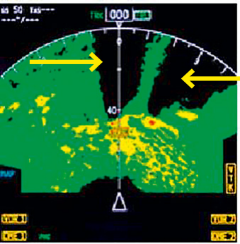
A black hole behind a red area on a weather radar display should always be considered as a zone that is potentially very active and shadows weather further down the scanned path.
(fig.5)
Section titled “(fig.5)”Attenuation caused by moderate to extreme precipitation
WEATHER RADAR TECHNOLOGY: THE DIFFERENT TYPES OF WEATHER RADAR
Section titled “WEATHER RADAR TECHNOLOGY: THE DIFFERENT TYPES OF WEATHER RADAR”In cooperation with its suppliers, Airbus has continuously and proactively supported weather radar technology evolution over the years.
These continuous improvements have allowed the crew to be provided with optimized observation features and weather threat assessment functions.
Radars with manual controls
Section titled “Radars with manual controls”Full manual control radars
Section titled “Full manual control radars”Early generations of radars are not equipped with an automatic tilt function; therefore the antenna tilt needs to be manually adjusted up and down as the flight progresses according to the aircraft’s altitude,
the expected weather on path and the ND range selection. Then the pilot needs to analyze and understand the individual radar slices of weather displayed in order to get an overall picture.
Early generation of full manual controlled radars without auto tilt are: Rockwell Collins WXR701X family up to weather radar transceiver Part Number 622-5132624 and Honeywell RDR-4B family up to weather radar transceiver Part Number 066-50008-0407.
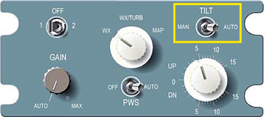
Autotilt radar (Honeywell RDR-4B family PN 066-50008-0409)
Section titled “Autotilt radar (Honeywell RDR-4B family PN 066-50008-0409)”(fi g.6) Honeywell Autotilt
Honeywell introduced the fi rst weather radar featuring an automatic tilt computation named “Autotilt”. When in Autotilt mode, the radar uses
the EGPWS terrain database and automatically adjusts the antenna tilt based on the aircraft position, altitude, and the selected ND range (fi g.6).
Fully automatic radars
Section titled “Fully automatic radars”Automatic radars optimize weather detection and decrease signifi cantly the pilots’ workload.
The next generation of radars included automatic functions, which:
-
Scan airspace ahead of the aircraft with multiple beams
-
Feature a three dimensional (3D) buffer to store weather data
-
Automatically compute and adjust the antenna tilt
-
Offer independent pilot control and display selection.
These new radars optimize weather detection and decrease signifi cantly the pilots’ workload necessary to understand the complete picture of the weather ahead.
A320 & A330 families: Multiscan radar (Rockwell Collins WXR-2100 family)
Section titled “A320 & A330 families: Multiscan radar (Rockwell Collins WXR-2100 family)”(fi g.7) Rockwell Collins Multiscan
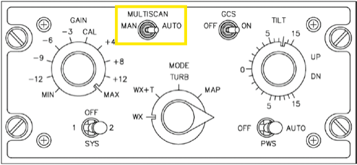
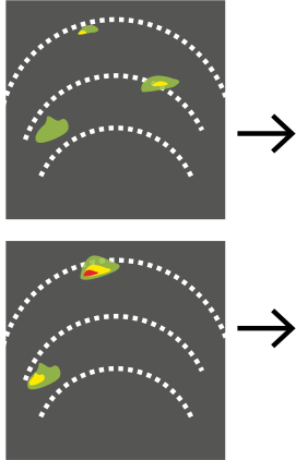
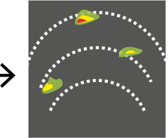
The WXR-2100 Multiscan weather radar is part of this new generation of weather radars that offers an automatic computation of tilt and gain control at all ranges, all altitudes and all times (fi g.7).
antenna tilt settings. The image that is displayed on the ND is the result of the stored and combined information from each beam.
The radar automatically adjusts the gain and tilt based on various parameters (aircraft altitude, geographical area, season, time of the day) to obtain the best weather display in each geographic region.
This weather radar is designed to work in Multiscan automatic mode. Pilots select only the desired range for the display and the radar alternatively scans at two
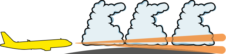
Upper Beam Lower Beam
Section titled “Upper Beam Lower Beam”Upper Beam
Lower Beam
Upper and lower beams data merge
+
Ground Clutter Suppression (GCS)
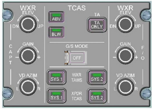
A320 & A330 & A350 & A380 families: Honeywell RDR-4000
Section titled “A320 & A330 & A350 & A380 families: Honeywell RDR-4000”The Honeywell RDR-4000 model is part of the new generation of weather radars including a 3D volumetric buffer.
It can probe hundreds of miles ahead (up to 320 NM on A320 & A330 families and up to 640 NM on A350 and
A380) to show the en route weather picture, as well as automatically scan from the ground up to 60 000 feet to provide information targeted at various altitudes. The required display data are then accessed from the 3D buffer (fi g.8 and 9).
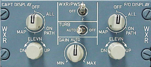
(fi g.8)
Section titled “(fi g.8)”Honeywell RDR-4000 control panel on A320 & A330 families
(fig.9) Honeywell RDR-4000 control panel on A350 & A380
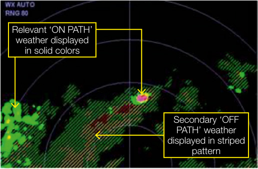
(fig.10) Honeywell RDR-4000 display
These enhanced weather radars are provided at Entry Into Service for new programmes (A380, A350) and as a retrofit option for A320 and A330 families.
‘OFF PATH’) depending on the flight profile. Weather conditions along the plane’s trajectory are displayed in solid colors, while more distant vertical echoes are shown in striped pattern to help pilots determine whether weather avoidance maneuver or rerouting is necessary (fig.10).
When it is activated in the automatic mode, the radar RDR-4000 takes into account a vertical trajectory envelope (nominally +/- 4000 ft) along the vertical flight path of the aircraft based on the flight path angle. It then defines if the weather echo is inside this envelope (relevant ‘ON PATH’) or not (secondary
The RDR-4000 can also be used in manual mode (elevation mode) as a tool for analyzing weather at userselected altitudes and thus, assess the vertical expansion and structure of convective clouds.
- as well as on the Vertical Display (VD) for views along the lateral flight path (in AUTO mode) or along the selected azimuth (in AZIM mode) (fig.11).
This system is available on the A380 and also on the A350 with an additional ‘weather ahead’ alerting function. On these aircraft, the weather displayed is a computed image on:
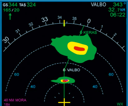
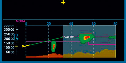
(fi g.11) Weather information displayed on the Vertical Display
Hail and lightning prediction: the new functions introduced by ‘step 2’ automatic radars
Section titled “Hail and lightning prediction: the new functions introduced by ‘step 2’ automatic radars”AHEAD’) to alert the crew when the ND is not in weather mode
In continuity of RDR-4000 and Multiscan WXR-2100, a new step of development recently introduced: - Hail and lightning prediction - Improved weather information.
-
Hazard functions offering:
-
Lightning and hail prediction
-
Rain Echo Attenuation Compensation Technique (REACT): this function indicates areas where the intensity of the radar echo has been attenuated by intervening weather.
Honeywell RDR-4000 (V2) includes new features to improve weather hazard assessment by automatically providing the following additional information (fi g.12) : - Weather alerting (‘WEATHER
- Extended turbulence detection (up to 60 NM instead of 40).
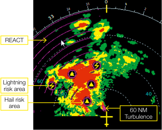
Honeywell RDR-4000 V2 display
Rockwell Collins Multiscan
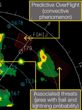
Section titled “Rockwell Collins Multiscan”WXR-2100 (V2) includes an automatic weather threat assessment (“Track While Scan” function). In continuity of the Multiscan, the aim of this version is to provide not only a depiction of the refl ectivity of surrounding weather cells, but also a threat assessment for each cell detected.
Weather cells are fi rst tracked and then, additional vertical scans are performed automatically to assess
the corresponding threat based on refl ectivity characteristics (fi g.13).
This new radar also provides hazard functions , namely:
-
Lightning and hail prediction
-
Predictive OverFlight (this function alerts the crew to growing cells that are potentially on the aircraft trajectory)
-
Improved turbulence detection able to display an additional level of moderate turbulence.
(fi g.13)
Section titled “(fi g.13)”Rockwell Collins Multiscan V2 threat detection and analysis
Honeywell RDR-4000 V2 and Rockwell Collins Multiscan WXR-2100 V2 weather radars were certifi ed in July 2015 for A320 and A330/A340 families and are available as retrofi t options.

Coming next… the future evolution of weather information
Section titled “Coming next… the future evolution of weather information”Airbus in cooperation with weather radars suppliers, maintain their efforts in designing and producing new weather surveillance functions. Today, at a research level, a strong focus is placed on three main dimensions with the aim to improve pilots’ awareness of the weather ahead.
1. High Altitude Ice Crystal (HAIC) detection to avoid flying in ice crystals areas.
Section titled “1. High Altitude Ice Crystal (HAIC) detection to avoid flying in ice crystals areas.”There are multiple threats attributed to ice crystals; for example, engine vibrations, engine power loss, engine damage or icing of air data probes. In fact, the formation of ice crystals at high altitude and their effect on aircraft performance is recognized as an industry wide issue. Airbus in particular is leading the HAIC research project with several partners. This project aims to characterize and identify the environmental conditions of ice crystals, to improve aircraft operations through the development of appropriate detection and awareness technologies to be fitted
on aircraft. The next generation of weather radars is expected to benefit from this research work and enable the detection of ice crystals to avoid convective weather linked to ice crystal icing.
2. Weather display fusion to offer a single display of weather data covering all weather threats.
Section titled “2. Weather display fusion to offer a single display of weather data covering all weather threats.”The feasibility of collecting all “weather on board” information together with weather information collected by the radar (reflectivity, turbulence and hazards) and merging them in a single display is currently being studied.
3. 3D weather analysis: automatic re-routing
Section titled “3. 3D weather analysis: automatic re-routing”Work is also being carried out to allow the automatic computation of an optimized deviation route based on: the actual weather (weather on board and radar data), the ongoing traffic and the stored flight plan. Such a function is expected to facilitate pilot’s decision making and re-routing planning if needed. Additionally it improves comfort.
PUTTING THEORY INTO PRACTICE: HOW TO MAKE AN OPTIMUM USE OF THE AIRBORNE WEATHER RADAR
Section titled “PUTTING THEORY INTO PRACTICE: HOW TO MAKE AN OPTIMUM USE OF THE AIRBORNE WEATHER RADAR”The weather radar is a tool for detecting, analyzing and avoiding adverse weather and turbulence. As with any other tool, adequate skills and the crew’s involvement are needed in order to use it efficiently. In fact, the management of adverse weather still relies primarily on the crew to actively monitor the meteorological situation throughout the flight, and make a full use of the available technology thanks to:
-
Awareness of weather radar capabilities and limitations, according to the specificities outlined in the FCOM and the manufacturer’s user guide.
-
Preflight briefing (knowledge of the route climatology and weather forecast –
charts and online simulation) and during flight (update on weather information) - Adapted use of the weather radar, with the crew regularly assessing the range, gain and tilt, and making use of weather threat assessment functions when available in order to display an optimum weather radar picture on the ND.
-
Regular manual vertical and horizontal scanning by the crew to increase situation awareness.
-
Correct understanding of the radar image displayed.
-
Adequate strategic (mid-term) and tactical (short term) decision making for trajectory planning.
How to optimally tune the weather radar and manage flights in convective weather?
Section titled “How to optimally tune the weather radar and manage flights in convective weather?”Flight planning: the importance of weather briefing and weather reports
Section titled “Flight planning: the importance of weather briefing and weather reports”Once airborne, the weather radar should be used and tuned regularly in combination with all available weather information.
Weather avoidance already starts in the briefing room before commencing the flight, with a thorough assessment of en-route weather and decisions on possible mitigation means.
Before boarding, a weather briefing should reveal areas of predicted significant weather activity. Equally, this briefing should include the assessment of typical weather patterns in the area. For example in the tropics, cumulonimbus intensity and development is greater at certain times of the day. The crew have the opportunity at this stage to plan a route to avoid active weather based
on both the weather briefing and their knowledge of local climatology. Changing the flight route could be an option as well as taking additional fuel for enhanced strategic and tactical options in flight. Once airborne, the weather radar should be used and tuned regularly in combination with all available information, e.g. preflight briefing, pilot’s knowledge and experience of the area’s typicality, reported turbulence, updated weather reports… If possible, the weather information should be updated in flight regularly. Information sought by ATC of turbulence encounters are an additional means.
INFORMATION
Section titled “INFORMATION”Safe operation in convective weather requires good theoretical knowledge of meteorology, particularly on the formation, development and characteristics of convective clouds in different regions of the world. This knowledge is usually provided in pilot licencing and operational training and is not covered by aircraft documentation (FCOM and FCTM).
Weather radar antenna tilt
Section titled “Weather radar antenna tilt”Effective management of the antenna tilt along with an appropriate ND range selection, are key tools to obtaining an informative weather radar display on the ND.
The flight crew needs to periodically scan: - Vertically, using the antenna tilt function - Horizontally, using the range change.
If available, the automatic mode should be used as the default mode (unless mentioned differently in the FCOM), for detection and initial evaluation of displayed weather. Then, if adverse weather is suspected (e.g. according to information gathered during the preflight briefing), manual control should be used regularly and actively to analyze the weather ahead.
The ND might not display cells at aircraft flight level, only cells that are cut by the radar beam are shown (fig.14). For this reason, the antenna tilt needs to be adjusted up and down regularly to scan weather ahead, and it needs to be adjusted to the ND range selection (except with the most recent radar models where this adjustment is made automatically).
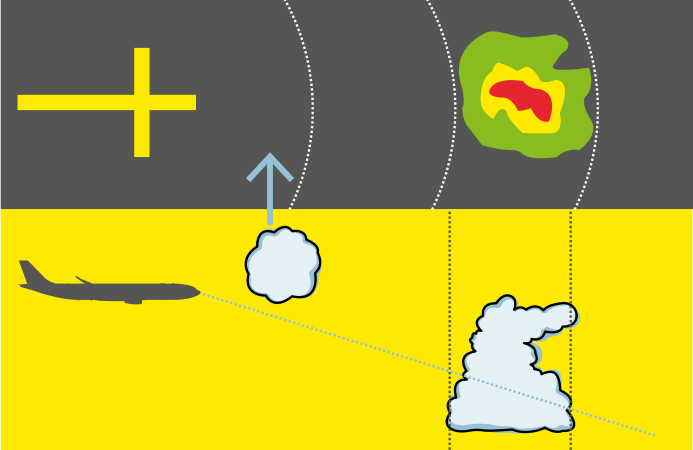
The automatic mode should be used as the default mode, for detection and initial evaluation of displayed weather. Then, manual control should be used periodically to analyze the weather.
(fig.14) Display along radar beam
BEST PRACTICE
Section titled “BEST PRACTICE”Even when the tilt is adjusted automatically, pilots are advised to reverse to the manual mode “MAN” regularly in order to scan the immediate weather ahead. This action allows the crew to assess the vertical structure and expansion of convective clouds.
Factors that can affect the relevancy of the ND display and that should trigger a tilt adjustment are:
-
A heading change
-
An altitude change, or even a regular flight profile change (e.g. from climb to cruise)
-
The shape of thunderstorms
-
A pilot report from another aircraft in the vicinity.
In the case of a change in heading or altitude, leaving the antenna tilt on auto may induce a risk of overlooking weather or underestimating the
severity of the weather. For example, at take-off or in climb, the tilt should be set up if adverse weather is expected above the aircraft. Figure 15 is an example of radar overshooting a
convective cell because the tilt is set incorrectly (too high in this case) while in the auto-tilt mode. When the antenna is tilted down, the ND shows a much stronger activity.
(fi g.15)
Section titled “(fi g.15)”Weather radar display at different tilt settings
Overscanning
Section titled “Overscanning”Correct storm display
Section titled “Correct storm display”Presence of yellow or green areas at high altitudes, above a red cell, may indicate a very turbulent area.
To analyze a convective cell, the fl ight crew should use the tilt knob to obtain a correct display and point the weather radar beam to the most refl ective part of the cell. At high altitude, a thunderstorm may contain ice particles that have low refl ectivity. If the tilt setting is not adapted, the ND may display only the upper (less refl ective) part of the convective cloud (overscanning). As a result, the fl ight crew may underestimate or not detect a thunderstorm. In order to get accurate weather detection, the weather radar antenna should also be pointed toward lower levels (i.e. below freezing level), where water can still be found. If a red area is found at a lower level, the antenna tilt should
then be used to scan the area vertically. Presence of yellow or green areas at high altitudes, above a red cell, may indicate a very turbulent area.
In most cases in flight, the adequate antenna tilt setting shows some ground returns at the top edge of the ND, which may be difficult to differentiate from genuine weather echoes. A change in antenna tilt rapidly changes the shape and color of ground returns and eventually causes them to disappear. This is not the case for weather echoes. Some weather radars are fi tted with a Ground Clutter Suppress (GCS) function. When turned ON, it suppresses the ground return from the display.
Display range management
Section titled “Display range management”DID YOU KNOW
Section titled “DID YOU KNOW”The FCTM provides useful guidance to correctly tune the weather radar in accordance with the fl ight phase.
To maintain a comprehensive situation awareness, the fl ight crew needs to monitor both the short-distance and long-distance weather. To this end, the crew should select different ranges on the Pilot Monitoring (PM) and Pilot Flying (PF) ND.
To avoid threatening convective weather, the fl ight crew should make deviation decisions while still at least 40 NM away;
therefore, the following ranges should be selected on the NDs:
-
Pilot Monitoring (PM) adjusts ranges to plan the long-term weather avoidance strategy (in cruise, typically 160 NM and below).
-
Pilot Flying (PF) adjusts ranges to monitor the severity of adverse weather, and decide on avoidance tactics (in cruise, typically 80 NM and below as required).
Course changes to avoid adverse weather should be determined using both displays. This prevents the “blind alley” effect: a course change that may
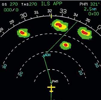
seem safe when using a low range ND display may reveal a blocked passage when observed at a higher range (fig.16).
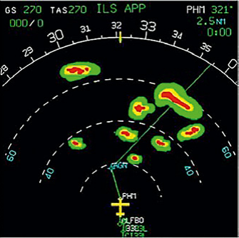
The crew should select different ranges on the Pilot Monitoring (PM) and Pilot Flying (PF) ND.
(fig.16) Blind alley effect
Section titled “(fig.16) Blind alley effect”Gain adjustment
Section titled “Gain adjustment”The sensitivity of the receiver may vary from one type of radar system to another. In the CAL (AUTO) position, the gain is in the optimum position to detect standard convective clouds. Manual settings are also available and can be used to analyze weather.
At low altitudes, reducing the gain might be justified for proper weather analysis. Due to increased humidity at lower levels, convective cells are usually more reflective and the weather radar display may have a tendency to show a lot of red areas. This can also be the case at higher altitude with
significant positive ISA deviations in a very humid atmosphere (typically the Indian monsoon). In these cases, slowly reducing the gain allows the detection of threatening areas: most red areas slowly turn yellow, the yellow areas turn green and the green areas slowly disappear. The remaining red areas – i.e. the red areas that are the last to turn yellow, - are the most active parts of the cell and must be avoided (fig.17).
At high altitudes, water particles are frozen and clouds are less reflective. In this case, gain should be increased for threat evaluation purposes.
Gain decreased
Section titled “Gain decreased”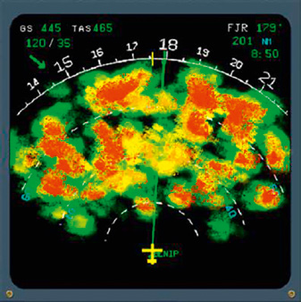
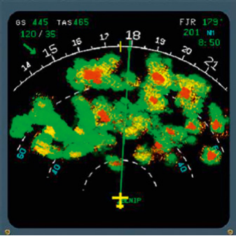
(fig.17) Effect of gain reduction
Turbulence and weather threats detection
Section titled “Turbulence and weather threats detection”The TURB function needs humidity; therefore clear air turbulence will not be displayed.
Turbulence can be diffi cult to predict, but signs such as frequent and strong lightning and/or the specifi c shape of clouds (see the next section) can alert the crew to the likely presence of severe turbulence. If necessary and when available (according to the standard of weather radar onboard), the TURB function can additionally be used to confi rm the presence of wet turbulence up to 40 NM (or 60 NM depending on
the radar standard) (fi g.18). Remember that the TURB function needs humidity; therefore clear air turbulence will not be displayed.
In addition, the flight crew may be alerted by visual cues provided by the latest generations of weather radars that offer weather threat assessment functions, such as hail or lightning predictions.
(fi g.18) Turbulence detection (in magenta)

HOW TO CORRECTLY TUNE THE WEATHER RADAR AT A GLANCE
Section titled “HOW TO CORRECTLY TUNE THE WEATHER RADAR AT A GLANCE”Study the weather radar’s specifi cities and limitations through Before fl ight the FCOM, FCTM and weather radar user guide. Gather information about the Before forecasted weather and update and regularly during fl ight: weather during fl ight briefi ng, route climatology knowledge, reported turbulence…
Set the antenna tilt to auto as the default mode for detection and initial evaluation of weather, and periodically use the manual modes to scan and analyze the weather situation.
During fl ight and periodically use the manual modes to scan and analyze the weather situation. In cruise the combination of the following ranges provides good weather awareness and allows to During fl ight avoid the “blind alley effect”: - 160 NM on the PM ND - 80 NM on the PF ND. Use gain in AUTO/CAL mode by default, then regularly reduce During fl ight the gain for weather severity assessment. Be attentive to the visual and oral cues provided by the weather During fl ight threat and hazard assessment functions (as installed).
Lithium batteries: safe to fl y?
Weather radar data understanding: how to decide on an effective avoidance strategy?
Section titled “Weather radar data understanding: how to decide on an effective avoidance strategy?”Before any avoidance maneuver is initiated, the analysis the fl ight crew makes of the weather radar display is essential. Doing so, the crew is able
to conduct an in-depth analysis of the convective weather situation on-path and off-path and eventually, initiate action if needed.
Correctly understanding the weather display is paramount
Section titled “Correctly understanding the weather display is paramount”(fi g.19)
Section titled “(fi g.19)”Indication of a threat: closely spaced areas of different colors
(fi g.20)
Section titled “(fi g.20)”Shapes indicative of adverse weather
conditions are too dangerous to fl y in.
After the weather radar has been tuned correctly, the data displayed should be supplemented with the available weather charts, reports and the meteorological knowledge of the pilot. Altogether these data enable the flight crew to get a complete weather picture and establish an “area of threat”. This “area of threat” corresponds to the zone where the fl ight crew estimates that the weather
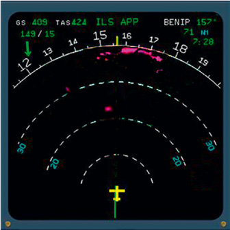
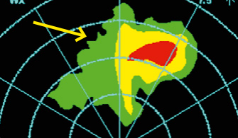
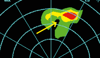
Some ND displays contain specific cues that should alert the fl ight crew. Clouds shapes, in addition to colors, should be observed carefully in order to detect adverse weather conditions. Closely spaced areas of different colors usually indicate highly turbulent zones (fi g.19).
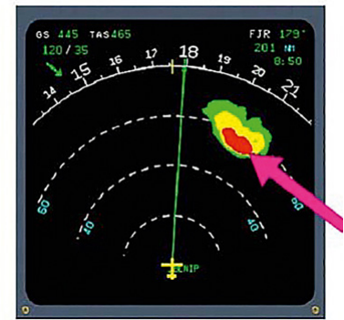
Some shapes are good indicators of severe hail that also indicate strong vertical drafts (fig.20). Finally, fast
changing shapes, whatever the form they take, also indicate high weather activity.
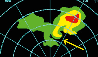
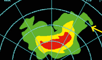
Finger
Hook
U-Shape
Scalloped Edges

Avoidance strategy
Section titled “Avoidance strategy”The fl ight crew needs to remain vigilant and active in using and tuning the weather radar in order to be able to initiate an avoidance maneuver as early as possible. Indeed, weather radar information becomes more intense as the aircraft gets nearer the convective weather zone, thus making avoidance decisions more diffi cult. For this reason, crews should consider a minimum distance of 40 NM from the convective cloud to initiate the avoidance maneuver.
Once the decision to deviate course has
been taken, fl ight crews need to bear in mind the following advisory precautions and limits before actually deciding the trajectory of the avoidance maneuver.
If possible, it is preferable to perform lateral avoidance instead of vertical avoidance. Indeed, vertical avoidance is not always possible (particularly at high altitude) due to the reduction of buffet and performance margins. In addition, some convective clouds may have a signifi cant build-up speed, that extends far above the radar visible top.
Consider a minimum distance of 40 NM from a threatening convective cloud to initiate the avoidance maneuver.
Lateral avoidance
Section titled “Lateral avoidance”-
When possible, it is advisable to try to avoid a storm by flying on the upwind side of a cumulonimbus. Usually, there is less turbulence and hail upwind of a convective cloud.
-
The “area of threat” identifi ed by the fl ight crew (e.g. a cumulonimbus cloud) should be cleared by a minimum of 20 NM laterally whenever possible
(fi g.21). An additional margin may be applied in case the convective clouds are very dynamic or have a signifi cant build-up speed.
- If the aircraft trajectory goes between several convective clouds, if possible maintain a margin of at least 40 NM with the identifi ed “area of threat”.
Vertical avoidance
Section titled “Vertical avoidance”- Do not attempt to fly under a convective cloud, even when you can see through to the other side, due to possible severe turbulence, windshear, microbursts and hail. If an aircraft must fl y below a convective cloud (e.g. during approach), then the fl ight crew should take into account
all indications (visual judgement, weather radar, weather report, pilot’s report, etc) before they take the fi nal decision.
- If overfl ying a convective cloud cannot be avoided, apply a vertical margin of 5 000 feet (fi g.21).
If possible, it is preferable to perform lateral avoidance instead of vertical avoidance.
(fig.21)
Section titled “(fig.21)”Lateral and vertical circumvention margins
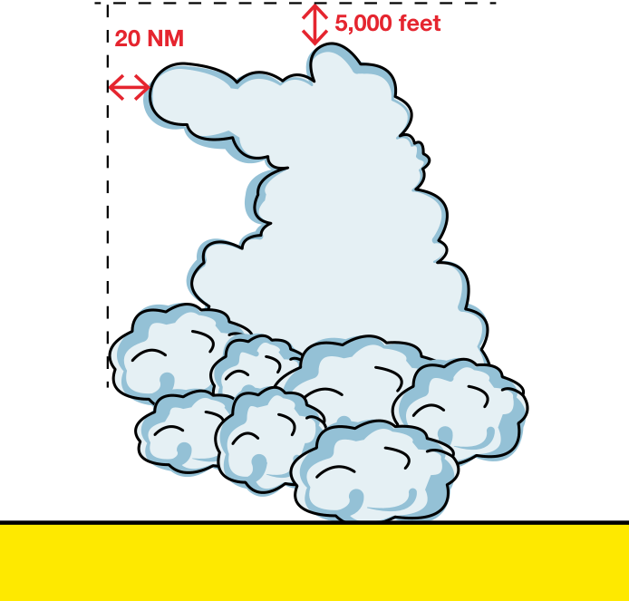
Figure 22 shows a typical weather radar display indicating multiple areas of severe weather. What route would look like the preferable option?
Route A:
Section titled “Route A:”this is the most direct route to destination but it navigates right through the most severe and active zone; therefore it is the path that carries the biggest risks and should not be an option.
Route C:
Section titled “Route C:”this route looks like a possible escape route because it goes around most of the storms by a wide safety margin. However, while doing so, the flight crew would need to keep a look at the cell to the left of this route, and see whether it develops rapidly or not. In addition, this route leads away from the initial flight plan and therefore it could have operational implications such as fuel consumption or delays.
Route B:
Section titled “Route B:”this route could be tempting since it requires little deviation to the mainstream route and it looks like the most active red areas are avoided. Nevertheless, this trajectory leads downwind of the convective area, thus increasing the risk of encountering severe weather. Additionally, the convective cells beneath might be developing fast and upwards, thus closing off the gap in between the red zones. Before this option is considered, the flight crew would need to tilt the radar antenna down to analyze weather and see what is below the apparent gap.
Route D:
Section titled “Route D:”this route would be the preferable option in terms of risks mitigation.
When faced with a situation where weather ahead reveals an extensive storm system, several options are always possible. Before the flight crew makes a decision, it is prudent to analyze weather carefully by scanning the vertical expansion of the various cells, and if possible, consider deviation to an alternate route.
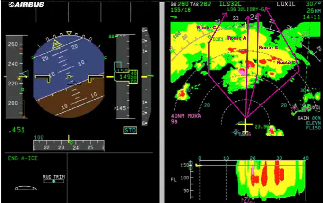
Available options to avoiding weather

Regardless of how you locate a severe weather area – visual, by radar, or from a report – a key parameter to successful route planning and avoidance strategy is time. The weather radar, and enhanced models more particularly, can help you to analyze and understand distant weather accurately and evaluate weather scenarios from a distance. This system is a key tool to planning ahead to avoid lastminute decisions, and making a decision on circumnavigating a nasty convective cell with a comfortable safety margin. In addition to technology, you need to stay active in maintaining situation awareness throughout the flight. Regularly complement the radar images displayed by a manual vertical scan of surrounding cells, as well as gain and tilt adjustments as required. Last but not least, adhere to your knowledge of meteorology basics, local climatology and weather briefing to adopt the best course of actions, and navigate safely, effectively and comfortably to destination.
Safety first, #22 July, 2016. Safety first is published by Airbus S.A.S. - 1, rond point Maurice Bellonte - 31707 Blagnac Cedex/France. Publisher and Editor: Yannick Malinge, Chief Product Safety Officer. Concept Design by Airbus Multi Media Support 20161577. Reference: GS 420.0045 Issue 22. Photos by Airbus, Lindner Fotografie, T. Denson, S. Ramadier, H. Goussé, P. Masclet, F. Lancelot, M. Lindner, P. Pigeyre.
Source: Airbus Safety First URL: https://safetyfirst.airbus.com/optimum-use-of-weather-radar/ Published: 2016-07-29 Magazine Issue: 2016-07 Category: Flight Ops, autotiltgain, cloud, collins, convective, cumulonimbus, hail, hailstorm, honeywell, ice, lightning, multiscan, radar, rain, rdr-4000, rockwell, storm, strikes, thunderstorm, tilt, turbulence, weather radar, windshear PDF: Original PDF
近年来,发生了多起乘客或机组人员因严重颠簸而受伤的航班事故。在其他一些案例中,飞机在遭遇雹暴后结构受到严重损坏。显然,恶劣天气会对航班的安全舒适完成构成威胁,因此需要及时探测并避开恶劣天气。
DAVID MARCONNET
Section titled “DAVID MARCONNET”飞行作业支援与培训标准安全提升
CHRISTIAN NORDEN
Section titled “CHRISTIAN NORDEN”飞行作业与培训政策总监
LAURENT VIDAL
Section titled “LAURENT VIDAL”监视系统经理
机载气象雷达系统是飞行员评估飞机前方对流天气强度的重要工具。在此方面,它使安全航迹的战略规划和战术规划成为可能。
气象雷达技术在过去几年中发展迅速,现已有一系列增强型产品可用。如果使用得当,这些产品可以显著减轻飞行员的工作负荷,同时大幅减少遭遇恶劣天气的次数。
本文概述了现有气象雷达技术,并提供有关如何调校系统和正确解读可用显示的信息和提示。
气象雷达原理与操作
Section titled “气象雷达原理与操作”飞机上安装的气象雷达系统为飞行员提供必要的信息,以避开——而非穿越——恶劣天气。要从气象雷达系统中获得最大收益,需要机组人员仔细优化其使用。这主要依赖于对天气现象的良好气象知识,以及对可用雷达功能的充分理解。
通过预见进行预防至关重要。
在恶劣天气中飞行:经验教训
Section titled “在恶劣天气中飞行:经验教训”航空业的经验表明,尽管飞机配备了机载气象雷达,但飞机仍然会进入非常活跃的对流云胞,导致人员受伤或飞机结构严重损坏 (图1)。
这些事件促使我们思考为什么会发生这种遭遇,并清楚地表明,通过预见进行预防至关重要。
(图1) 遭遇冰雹后的天线罩和风挡
说到理解为什么装有技术先进的气象雷达的飞机会进入如此不利的天气模式,我们必须认识到,最大限度地发挥机载技术的作用只是答案的一部分。恶劣天气避让策略的一个关键要素是机组人员对整体气象状况的主动监控,此外还要最佳使用气象雷达并正确理解所显示的信息。我们不能忘记,气象雷达只是辅助工具,而机组人员对天气状况的总体评估起着核心作用。
积雨云(通常称为”雷暴”)的结构是怎样的?
Section titled “积雨云(通常称为”雷暴”)的结构是怎样的?”对飞机有三种常见威胁:颠簸(由两团以不同速度移动的气团碰撞引起)、冰雹和风切变。这三种都是雷暴的副产品。
了解积雨云的结构和演变是躲避相关天气干扰的关键。
与积雨云相关的颠簸并不局限于云内部。因此,当在已发展出积雨云的区域飞行时,有必要按照本文总结的天气避让建议采取措施。
积雨云中冰雹的存在随高度和风向而变化:
-
在 FL 100 以下,冰雹在云体下方、云中或云周围(最远 2 海里)遇到的可能性相同。
-
在 FL 100 至 FL 200 之间,约 60% 的冰雹在积雨云内遇到,40% 在云外的砧状云下方遇到。
-
在 FL 200 以上,冰雹最有可能在云内遇到。
当在云外遇到冰雹时,通常在积雨云的下风侧冰雹威胁更大,因为湿气被强上升气流带到云内,然后冻结成冰雹,再被吹向下风侧。自相矛盾的是,在潮湿空气中遇到冰雹的风险反而比在干燥空气中低。实际上,空气中的水分起到热导体的作用,有助于融化冰雹。
相对于积雨云位置遭遇冰雹的风险
气象雷达原理
Section titled “气象雷达原理”掌握雷达原理对于准确调校该系统并正确解读气象雷达显示至关重要。
气象探测基于水滴的反射率**(图2)**。气象回波在导航显示器(ND)上显示时采用彩色标度,从红色(高反射率)到绿色(低反射率)。
气象雷达回波强度随水滴的大小、成分和数量而变化。例如,水滴的反射率是同等大小冰粒的五倍。
轻微降雨的回波在正常模式下显示为绿色,但当存在高强度湍流活动时则显示为品红色。TURB功能在大多数气象雷达上仅在40海里范围内有效(多普勒测量能力),且仅应用于湿性湍流。
气象雷达操作
Section titled “气象雷达操作”机组使用四个功能来操作雷达:
对最佳倾斜设置有重要影响。
-
**增益控制:**调节接收机灵敏度。
-
天线倾斜角:波束中心与地平线之间的夹角(图3)。
-
**雷达模式:**气象(WX)或气象+湍流(WX+T)。
-
**ND量程控制:**调节显示范围。
在空中客车机队上,所有气象雷达均具备完整功能,可进行湿性湍流探测。
(图2) 气象雷达原理
每种型号的气象雷达都有其独特性。要获取每种气象雷达型号的特性、限制和操作建议的全部信息,需要研究雷达制造商的用户指南。
(图3) 倾斜角的定义
气象雷达的限制
Section titled “气象雷达的限制”气象雷达探测能力
Section titled “气象雷达探测能力”反射率与可能遇到的风险程度并非直接成正比。
(图4) 积雨云的反射图像
气象雷达的局限性之一是它只能探测液态水的存在。其结果是,雷暴在不同高度上的反射率并不相同,因为大气中液态水的含量随高度降低**(图4)**。然而,对流云及其相关威胁可能远超气象雷达的探测上限(称为”雷达顶部”)。这意味着反射率与可能遇到的风险程度并非直接成正比:即使雷达回波较弱,对流云也可能具有危险性。
在赤道陆地区域,对流的干燥空气产生大范围上升气流,所形成的天气单体比中纬度对流单体的反射率低得多。然而,这些云层内部或上方的湍流强度可能高于气象雷达显示的图像。此外,靠近海面的空气可能非常湿润。在这种情况下,热对流会产生充满水分的云层:这些云层反射率很高,但未必构成重大威胁。
因此,必须充分了解气象雷达的局限性,并结合机组人员的基础气象学知识以及尽可能的目视观察来加以补充。
(图4) 积雨云的反射图像
气象雷达无法探测:
Section titled “气象雷达无法探测:”-
降雨 - 冰晶、干冰雹* 和雪 - 湿冰雹和湿性湍流 - 晴空湍流 - 风切变 - 沙尘暴(固态粒子对雷达波束几乎透明)
-
闪电*
- 最新一代气象雷达提供冰雹和闪电预测功能(见下文相关章节)。
波束衰减现象
Section titled “波束衰减现象”气象雷达的另一个局限性称为”遮蔽”或”衰减”。气象雷达显示依赖信号回波:降水越剧烈,雷达能够穿透的距离越短。因此,当雷达回波无法完成穿越强降水的双向传播时,就会产生”遮蔽”效应。结果有两方面。首先,天气目标的尺寸、形状和强度可能无法准确显示给飞行员。原本看起来很薄或不存在的一条降水带**(图5)**实际上可能是一片更大降水区的前沿。其次,任何位于强遮蔽云体后方的天气目标都将无法被探测到。这可能导致在绕过云体后才发现意想不到的天气。
(图5) 雷达回波的遮蔽效应
气象雷达显示上红色区域后面的黑色空洞始终应被视为潜在高度活跃的区域,会遮蔽扫描路径更远处的天气。
中度至极端降水引起的衰减
气象雷达技术:不同类型的气象雷达
Section titled “气象雷达技术:不同类型的气象雷达”空客与其供应商合作,多年来持续积极地推动气象雷达技术的发展。
这些持续改进使机组能够获得优化的观测功能和天气威胁评估功能。
手动控制雷达
Section titled “手动控制雷达”全手动控制雷达
Section titled “全手动控制雷达”早期代际的雷达未配备自动倾仰功能;因此,在飞行过程中需根据飞机高度、航路上预期天气状况以及所选的 ND(导航显示)范围手动调整天线倾仰角。随后,飞行员需要分析和理解所显示的天气雷达切片图像,以获得整体天气态势。
不带自动倾仰功能的全手动控制雷达早期代际产品包括:Rockwell Collins WXR701X 系列(气象雷达收发器件号至 622-5132624)以及 Honeywell RDR-4B 系列(气象雷达收发器件号至 066-50008-0407)。
自动倾仰雷达(Honeywell RDR-4B 系列,件号 066-50008-0409)
Section titled “自动倾仰雷达(Honeywell RDR-4B 系列,件号 066-50008-0409)”(图 6) Honeywell 自动倾仰
Honeywell 推出了首款具备自动倾仰计算功能的气象雷达,名为“自动倾仰”(Autotilt)。当处于自动倾仰模式时,雷达使用 EGPWS(增强型近地警告系统)地形数据库,并根据飞机位置、高度及所选的 ND 范围自动调整天线倾仰角**(图 6)**。
自动雷达可优化天气探测能力,并显著降低飞行员的工作负荷。
新一代雷达具备自动功能,包括:
- 使用多波束扫描飞机前方空域
- 采用三维(3D)缓冲存储天气数据
- 自动计算并调整天线倾仰角
- 提供独立的飞行员控制和显示选择功能。
这些新型雷达可优化天气探测能力,并显著降低飞行员了解前方天气全貌所需的工作负荷。
A320 和 A330 系列:Multiscan(多扫描)雷达(Rockwell Collins WXR-2100 系列)
Section titled “A320 和 A330 系列:Multiscan(多扫描)雷达(Rockwell Collins WXR-2100 系列)”(图 7) Rockwell Collins 多扫描雷达
WXR-2100 多扫描气象雷达属于这一新一代气象雷达,可在所有范围、所有高度和所有时间提供自动倾仰角和增益控制计算**(图 7)**。
天线倾仰角设置。ND 上显示的图像是每个波束存储和组合信息的结果。
雷达根据各种参数(飞机高度、地理区域、季节、一天中的时间)自动调整增益和倾仰角,以在每个地理区域获得最佳天气显示。
该气象雷达设计为在 Multiscan 自动模式下工作。飞行员仅需选择所需的显示范围,雷达便会以两个不同的倾仰角交替扫描。
上波束 下波束
Section titled “上波束 下波束”上波束
下波束
上下波束数据融合
+
地杂波抑制(GCS)
A320、A330、A350 和 A380 系列:Honeywell RDR-4000
Section titled “A320、A330、A350 和 A380 系列:Honeywell RDR-4000”Honeywell RDR-4000 型属于新一代气象雷达,包含 3D 体积缓冲功能。
它可探测数百英里前方(空客 A320 和 A330 系列最远 320 海里,A350 和 A380 最远 640 海里),显示航路天气态势,并自动从地面扫描至 60,000 英尺高度,以提供针对不同高度的信息。然后从 3D 缓冲中访问所需的显示数据**(图 8 和 9)**。
空客 A320 和 A330 系列上的 Honeywell RDR-4000 控制面板
(图 9) 空客 A350 和 A380 上的 Honeywell RDR-4000 控制面板
(图 10) Honeywell RDR-4000 显示
这些增强型气象雷达在新项目投入运营(A380、A350)时提供,也可作为空客 A320 和 A330 系列的改装选项。
“偏离航迹”)取决于飞行剖面。沿飞机航迹的天气状况以实心颜色显示,而更远处的垂直回波则以条纹图案显示,以帮助飞行员判断是否需要采取天气规避机动或重新规划路线**(图 10)**。
当在自动模式下激活时,RDR-4000 雷达根据飞行航迹角,沿飞机垂直飞行轨迹考虑一个垂直轨迹包线(标称值 ±4,000 英尺)。然后判断天气回波是否在此包线内(相关“沿航迹”)或之外(次要
RDR-4000 也可使用手动模式(仰角模式)作为分析用户选定高度处天气的工具,从而评估对流云的垂直扩展和结构。
- 以及在垂直显示(VD)上显示沿侧向航迹的视图(自动模式)或沿选定方位角的视图(方位角模式)(图 11)。
该系统可用于 A380,也可在 A350 上使用并附加“前方天气”警戒功能。在这些飞机上,显示的天气是计算后的图像:
(图 11) 垂直显示上的天气信息
冰雹和闪电预测:‘step 2’自动气象雷达引入的新功能
Section titled “冰雹和闪电预测:‘step 2’自动气象雷达引入的新功能”继RDR-4000和Multiscan WXR-2100之后,近期又推出了新的开发阶段:- 冰雹和闪电预测 - 改进的气象信息
-
危险功能,提供:
-
闪电和冰雹预测
-
雨回波衰减补偿技术(REACT):该功能指示因中间气象条件导致雷达回波强度衰减的区域
Honeywell RDR-4000 (V2) 包含新功能,通过自动提供以下附加信息来改进天气危险评估 (图12):- 天气告警(‘WEATHER AHEAD’):当ND未处于气象模式时提醒机组 - 扩展湍流探测(可达60海里,而非40海里)
Honeywell RDR-4000 V2显示器
罗克韦尔柯林斯 Multiscan
Section titled “罗克韦尔柯林斯 Multiscan”WXR-2100 (V2) 包含自动天气威胁评估功能(“Track While Scan”扫描时追踪功能)。在Multiscan的基础上,该版本的目的是不仅提供周围气象单体的反射率图像,还对每个探测到的单体进行威胁评估。
首先对气象单体进行追踪,然后自动执行额外的垂直扫描,以根据反射率特征评估相应的威胁 (图13)。
该新型雷达还提供危险功能,即:
-
闪电和冰雹预测
-
Predictive OverFlight(预测飞越):该功能提醒机组注意可能在航迹上的发展中的气象单体
-
改进的湍流探测,能够显示额外的 Moderate 级湍流
罗克韦尔柯林斯 Multiscan V2 威胁探测与分析
Honeywell RDR-4000 V2 和罗克韦尔柯林斯 Multiscan WXR-2100 V2 气象雷达于2015年7月获得A320和A330/A340系列飞机认证,并可作为改装选项提供。
即将到来……气象信息的未来发展
Section titled “即将到来……气象信息的未来发展”空客与气象雷达供应商合作,继续致力于设计和生产新的气象监视功能。目前,在研究层面,重点放在三个主要方向,以提高飞行员对前方天气的认知能力。
1. 高空冰晶(HAIC)探测,避免进入冰晶区域飞行
Section titled “1. 高空冰晶(HAIC)探测,避免进入冰晶区域飞行”冰晶存在多种威胁:例如,发动机振动、发动机功率损失、发动机损坏或空速管结冰。实际上,高空冰晶的形成及其对飞机性能的影响已被业界公认为一个重要问题。空客牵头开展HAIC研究项目,与多个合作伙伴共同推进。该项目旨在表征和识别冰晶的环境条件,通过开发适当的探测和预警技术来改善飞机运行。下一代气象雷达有望从这项研究工作中受益,实现冰晶探测,从而规避与冰晶结冰相关的对流天气。
2. 气象显示融合,为所有天气威胁提供单一气象数据显示
Section titled “2. 气象显示融合,为所有天气威胁提供单一气象数据显示”目前正在研究收集所有”机载气象”信息以及雷达收集的气象信息(反射率、湍流和危险)的可行性,并将其融合在单一显示器上。
3. 三维气象分析:自动重新规划航路
Section titled “3. 三维气象分析:自动重新规划航路”同时还在开展相关工作,以实现基于以下条件自动计算优化偏航路径:实际天气(机载气象信息和雷达数据)、当前交通状况以及存储的飞行计划。此类功能预计将便于飞行员在需要时做出决策和重新规划航路。此外,还能提高乘坐舒适度。
将理论付诸实践:如何最佳使用机载气象雷达
Section titled “将理论付诸实践:如何最佳使用机载气象雷达”气象雷达是用于探测、分析和规避不利天气和湍流的工具。与任何其他工具一样,需要适当的技能和机组的积极参与才能有效使用。事实上,不利天气的管理仍然主要依靠机组在整个飞行过程中主动监视气象状况,并通过以下方式充分利用可用技术:
-
了解天气雷达的能力和局限性,参照FCOM和制造商用户指南中的具体说明
-
飞行前简报(掌握航线气候学和天气预报——图表和在线模拟)以及飞行中(更新天气信息)
-
适当地使用气象雷达,机组定期评估探测范围、增益和俯仰角,并在可用时利用天气威胁评估功能,以便在ND上显示最佳气象雷达图像
-
定期进行手动垂直和水平扫描,增强态势感知能力
-
正确理解所显示的雷达图像
-
适当进行战略(中长期)和战术(短期)决策以规划航迹
如何最佳调节气象雷达并在颠簸天气中管理飞行?
Section titled “如何最佳调节气象雷达并在颠簸天气中管理飞行?”飞行计划:气象简报和气象报告的重要性
Section titled “飞行计划:气象简报和气象报告的重要性”一旦起飞,气象雷达应结合所有可用气象信息定期使用和调节。
天气规避在飞行前始于简报室,需对航路天气进行全面评估,并决定可能的缓解措施。
登机前,气象简报应揭示预计将出现重要天气活动的区域。同样,该简报应包括对当地典型天气形势的评估。例如在热带地区,积雨云的强度和演变在一天中的某些时段更为显著。机组人员此时有机会根据气象简报和对当地气候的了解,规划一条规避活跃天气的航线。改变飞行路线是一种选择,携带额外燃油以增强飞行中的战略和战术选项也是可行的。一旦起飞,气象雷达应结合所有可用信息定期使用和调节,例如:飞行前简报、飞行员对该地区典型天气的知识和经验、报告的颠簸情况、最新气象报告……如可能,气象信息应在飞行中定期更新。空中交通管制询问的颠簸遭遇报告是额外的参考手段。
在颠簸天气中安全运行需要对气象学有扎实的理论知识,特别是对不同地区颠簸云的形成、发展和特征的了解。此类知识通常在飞行员执照培训和运行培训中提供,飞机文档(FCOM和FCTM)中未涉及。
气象雷达天线倾斜角
Section titled “气象雷达天线倾斜角”天线倾斜角的有效管理与适当的ND范围选择,是在ND上获得有价值气象雷达显示的关键工具。
飞行机组需要定期扫描:
- 垂直方向,使用天线倾斜功能
- 水平方向,使用范围变化
如果有,自动模式应作为默认模式使用(除非FCOM中另有说明),用于检测和初步评估显示的天气。然后,如果怀疑存在恶劣天气(例如根据飞行前简报期间收集的信息),应定期主动使用手动控制来分析前方天气。
ND可能不显示飞机飞行高度处的气象单体,仅显示被雷达波束切割的气象单体 (图14)。因此,天线倾斜角需要定期上下调节以扫描前方天气,并且需要根据ND范围选择进行调整(除了最新的雷达型号,这些调整是自动进行的)。
自动模式应作为默认模式使用,用于检测和初步评估显示的天气。然后,应定期使用手动控制来分析天气。
(图14) 沿雷达波束的显示
即使倾斜角自动调节,也建议飞行员定期切换回手动模式”MAN”以扫描前方天气。此动作使机组能够评估颠簸云的垂直结构和扩展范围。
可能影响ND显示相关性并应触发倾斜角调整的因素包括:
- 航向变化
- 高度变化,甚至常规飞行剖面变化(例如从爬升到巡航)
- 雷暴形状
- 附近另一架飞机的飞行员报告
如果航向或高度发生变化,将天线倾斜角保持在自动模式可能导致忽略天气或低估天气严重性的风险。例如,在起飞或爬升时,如果预计飞机上方有恶劣天气,应设置倾斜角。图15 是雷达过扫一个颠簸单体的示例,因为在自动倾斜模式下倾斜角设置不正确(此案例中设置过高)。当天线向下倾斜时,ND显示更强的活动性。
不同倾斜角设置下的气象雷达显示
正确风暴显示
Section titled “正确风暴显示”红色单体上方的高空出现黄色或绿色区域可能表明存在严重颠簸区域。
为了分析颠簸单体,飞行机组应使用倾斜旋钮获得正确显示,并将气象雷达波束指向单体最具反射性的部分。在高空,雷暴可能含有反射性低的冰粒。如果倾斜角设置不适配,ND可能仅显示颠簸云的上部(反射性较低的部分)(过扫)。因此,飞行机组可能低估或未能探测到雷暴。为了获得准确的气象探测,气象雷达天线也应指向更低的高度层(即冰冻层以下),因为那里仍可能有液态水。如果在较低高度层发现红色区域,则应使用天线倾斜角垂直扫描该区域。红色单体上方的高空出现黄色或绿色区域可能表明存在非常颠簸的区域。
在大多数飞行情况下,适当的天线倾斜角设置会在ND顶部边缘显示一些地面回波,可能难以与真正的天气回波区分开来。天线倾斜角的变化会迅速改变地面回波的形状和颜色,最终使其消失。天气回波则不会出现这种情况。部分气象雷达配备了地面杂波抑制(GCS)功能。开启后,它会从显示中抑制地面回波。
显示范围管理
Section titled “显示范围管理”《FCTM》提供了根据飞行阶段正确调谐气象雷达的有用指导。
为了保持全面的情景意识,机组需要同时监控短距离和长距离天气。为此,机组应在监控飞行员(PM)和主飞飞行员(PF)的导航显示器(ND)上选择不同的范围。
为避开具有威胁性的对流天气,机组应在距离天气至少40海里时做出绕飞决策;因此,应在导航显示器上选择以下范围:
-
监控飞行员(PM)调整范围以规划长期绕飞策略(巡航阶段通常为160海里及以下)。
-
主飞飞行员(PF)调整范围以监控恶劣天气的严重程度,并决定绕飞策略(巡航阶段通常为80海里及以下,按需调整)。
避绕恶劣天气的航向改变应综合两个显示器来确定。这可以防止“死胡同”效应:当使用低范围导航显示器显示时看似安全的航向改变,在较高范围观察时可能会发现前方通路已被遮挡 (图16)。
机组应在监控飞行员(PM)和主飞飞行员(PF)的导航显示器上选择不同的范围。
(图16) 死胡同效应
Section titled “(图16) 死胡同效应”接收机的灵敏度可能因雷达系统类型的不同而有所差异。在CAL(自动)位,增益处于探测标准对流云的最佳位置。也可使用人工设置来分析天气。
在低空高度,降低增益可能有助于正确分析天气。由于低层湿度增加,对流单体通常具有更强的反射性,气象雷达显示器可能倾向于显示大量红色区域。在高空且存在显著正ISA偏差的非常潮湿大气中(通常是印度季风区)也可能出现这种情况。在这些情况下,逐步降低增益可以探测到威胁区域:大多数红色区域会逐渐变为黄色,黄色区域变为绿色,绿色区域逐渐消失。剩余的红色区域——即最后变为黄色的红色区域——是单体中最活跃的部分,必须避开 (图17)。
在高空,水粒处于冻结状态,云层反射性较弱。在这种情况下,应增加增益以进行威胁评估。
(图17) 增益降低的效果
颠簸和天气威胁探测
Section titled “颠簸和天气威胁探测”TURB功能需要水汽;因此晴空颠簸不会显示。
颠簸可能难以预测,但频繁而强烈的闪电和/或云的特殊形状(见下一节)等迹象可提醒机组注意可能存在严重颠簸。如有必要且可用时(根据机载气象雷达标准),TURB功能还可用于确认最多40海里(或60海里,取决于雷达标准)的湿颠簸存在 (图18)。请记住,TURB功能需要水汽;因此晴空颠簸不会显示。
此外,机组还可能通过最新一代气象雷达提供的天气威胁评估功能(如冰雹或闪电预测)获得的目视提示得到警示。
(图18) 颠簸探测(品红色显示)
一目了然:如何正确调谐气象雷达
Section titled “一目了然:如何正确调谐气象雷达”| 阶段 | 操作 |
|---|---|
| 飞行前 | 通过FCTM、《FCOM》和气象雷达用户指南了解气象雷达的特点和限制。收集预报天气信息,并在飞行前及飞行期间定期更新:天气简报、航线气候学知识、报告的颠簸情况…… |
| 飞行前及飞行期间 | 将天线倾斜角设置为自动作为探测和初步评估天气的默认模式,并定期使用人工模式扫描和分析天气状况。 |
| 飞行期间 | 使用以下范围组合可提供良好的天气意识并避免“死胡同效应”:- PM导航显示器上160海里 - PF导航显示器上80海里 |
| 飞行期间 | 默认使用自动/CAL模式的增益,然后定期降低增益进行天气严重程度评估。注意天气威胁和危险评估功能(如已安装)提供的目视和语音提示。 |
锂电池:飞行安全吗?
了解天气雷达数据:如何确定有效的绕飞策略?
Section titled “了解天气雷达数据:如何确定有效的绕飞策略?”在启动任何绕飞机动之前,机组对天气雷达显示器的分析至关重要。通过分析,机组能够对航路上及航路外的对流天气状况进行深入分析,并在必要时采取行动。
正确理解天气显示至关重要
Section titled “正确理解天气显示至关重要”威胁警示:不同颜色的密集区域
表明存在危险天气条件的形状不宜飞入。
在正确调谐天气雷达后,显示的数据应结合可用的天气图、报告以及飞行员的气象知识进行综合分析。所有这些数据使机组能够获得完整的天气图像,并确定“威胁区域”。“威胁区域”对应于机组评估天气状况将对其造成影响的区域。
某些 ND(导航显示器)包含特定的警示提示,机组应保持警觉。除了颜色之外,还应仔细观察云体形状,以探测不利的天气状况。不同颜色的密集区域通常表示存在高度湍流区**(图19)**。
某些形状是强冰雹的良好指示,同时也表明存在强烈的垂直气流**(图20)**。此外,形状快速变化的区域,无论其呈现何种形态,都表明天气活动剧烈。
指状
钩状
U形
扇贝状边缘
机组需要在使用和调谐天气雷达时保持警惕和主动,以便能够尽早启动绕飞机动。事实上,随着飞机接近对流天气区域,天气雷达信息的强度会增加,使绕飞决策更加困难。出于此原因,机组应在距对流云体至少 40 NM 处开始考虑实施绕飞机动。
一旦做出偏航决定,机组在实际确定绕飞机动轨迹之前,需要牢记以下咨询注意事项和限制。
如果可能,优选横向绕飞而非垂直绕飞。事实上,由于湍流边界和性能裕度的减小,垂直绕飞并非总是可行(特别是在高空)。此外,某些对流云体的增长速度可能很快,且向上延伸的高度远超过雷达可见顶部。
考虑在距威胁性对流云体至少 40 NM 处开始实施绕飞机动。
-
如果可能,建议尝试从积雨云的迎风侧绕飞。通常,对流云体迎风侧的湍流和冰雹较少。
-
机组识别的“威胁区域”(例如积雨云)应尽可能保持至少 20 NM 的横向距离**(图21)**。如果对流云体非常活跃或具有显著的快速增长速度,可额外增加裕度。
-
如果飞机轨迹需要穿越多块对流云体之间,应尽可能与已识别的“威胁区域”保持至少 40 NM 的裕度。
-
不要尝试从对流云体下方飞过,即使可以看到另一侧,因为可能存在严重湍流、风切变、微下击暴流和冰雹。如果飞机必须在对流云体下方飞行(例如在进近期间),机组应在做出最终决定之前综合考虑所有指示(目视判断、天气雷达、天气报告、飞行员报告等)。
-
如果无法避免飞越对流云体,应保持 5 000 英尺的垂直裕度**(图21)**。
如果可能,优选横向绕飞而非垂直绕飞。
横向和垂直绕飞裕度
图 22 显示了一个典型的天气雷达显示器,指示出多个严重天气区域。哪条航路是优选方案?
这是前往目的地最直接的航路,但它正好穿过最严重和最活跃的天气区域;因此这条路径风险最大,不应作为选项。
这条航路看起来是一条可能的脱离航路,因为它以较大的安全裕度绕过了大部分雷暴区域。然而,在这样做时,机组需要留意该航路左侧的云体,观察它是否迅速发展的。此外,这条航路会远离初始飞行计划,因此可能产生运营影响,例如燃油消耗或延误。
Route B:
Section titled “Route B:”这条航路看起来很有吸引力,因为它只需稍微偏离主流航路,而且看起来最活跃的红色区域都被避开了。然而,这条轨迹位于对流区域的下风向,因此增加了遇到恶劣天气的风险。此外,下方的对流云可能正在快速发展上升,从而封闭红色区域之间的缝隙。在考虑此选项之前,机组需要将雷达天线下倾以分析天气状况,查看看起来有缝隙的区域下方是什么情况。
Route D:
Section titled “Route D:”这条航路在风险缓解方面将是最佳选择。
当面对前方天气显示大范围雷暴系统的情况时,通常有几种选择。在机组做出决定之前,明智的做法是仔细分析天气,扫描各个云体的垂直发展情况,如果可能的话,考虑改航到备用航路。
规避天气的可用选择
无论你如何定位恶劣天气区域——目视、通过雷达还是根据报告——成功航路规划和避让策略的一个关键参数是时间。天气雷达,特别是增强型模型,能够帮助你准确分析和理解远处的天气状况,并从远距离评估天气情景。该系统是提前规划以避免临时决定的关键工具,也是以舒适的安全裕度决定绕飞恶劣对流云的关键工具。除了技术手段之外,你还需在整个飞行过程中积极保持态势感知。定期用手工垂直扫描周围云体来补充雷达显示的图像,并根据需要调整增益和下倾角。最后但同样重要的是,遵循你对气象学基础、当地气候和天气简报的认知,采取最佳行动,安全、有效且舒适地飞抵目的地。
Safety first, #22 July, 2016. Safety first is published by Airbus S.A.S. - 1, rond point Maurice Bellonte - 31707 Blagnac Cedex/France. Publisher and Editor: Yannick Malinge, Chief Product Safety Officer. Concept Design by Airbus Multi Media Support 20161577. Reference: GS 420.0045 Issue 22. Photos by Airbus, Lindner Fotografie, T. Denson, S. Ramadier, H. Goussé, P. Masclet, F. Lancelot, M. Lindner, P. Pigeyre.