Airbus Crosswind Development and Certification
Source: Airbus Safety First URL: https://safetyfirst.airbus.com/airbus-crosswind-development-and-certification/ Published: 2013-01-14 Magazine Issue: 2013-02 Category: Archive PDF: Original PDF
Safety
Frank CHAPMAN
Section titled “Frank CHAPMAN”Experimental Test Pilot
1. Introduction
Section titled “1. Introduction”This article is one of a series in which we in Airbus try to create a bridge of information across the gap that exists between the manufacturers world of certification and the operators day to day environment.
At first glance, the issue of crosswind certification for a large transport aircraft may seem simple. The following is an extract from the EASA CS25.237(a) requirements:
A 90 deg cross component of wind velocity, demonstrated to be safe for take-off and landing must be established for dry runways and must be at least 20 kt or Vs MLW (1 g stall speed at Max Landing Weight) whichever is greater, except that it need not exceed 25 kt.
However, the subject is far more complicated than this short sentence may lead you to believe. So how do we deal with crosswinds during flight test and certification and what are the implications for operators?
2. History
Section titled “2. History”Historically, there were two methods of computation. For early certifications, ATC tower winds were used to assess the level of crosswind experienced at take-off and landing by flight test crews. This was done with an old fashioned anemometric recording system, registering wind values at a nominal 10 metres above ground level. This method evolved into using aircraft generated cross wind data by calculating the 10 m high wind using the difference between the True Air Speed (TAS) vector and the IRS computed Ground Speed (GS) vector during a 20 second period (+_10 sec) around takeoff and landing. However, as natural IRS drift creates inaccuracy, this had to be taken into account. The drift value had to be periodically measured in order to correct IRS Ground Speed. With the advent of Differential GPS (DGPS) and more recent on-board instrumentation systems, the GS vector is now calculated using highly accurate data and, therefore, this correction is no longer necessary.
In the early days of certification, when using tower winds, the aver-
age wind values were taken over the previous two minutes and the gust values over the previous 10 min period. Although ICAO considers wind gusts only if the peak value exceeds the two minute average by 10 kt, some airport weather services provide gust values lower than 10 kt. This method is still used for the broadcast of ATC tower winds. With the new flight test methodology, however, a much more representative assessment of the aircraft capability is achieved.
With the early Airbus certifications, we provided ‘Average plus Gust’ values in our FCOMs. However, it was felt by many that this format complicated the decision making process. Therefore, following a period of study beginning in 2004 we have now moved to a ‘Single Value, Gust Included’. This effectively means that a direct comparison of the maximum demonstrated value (provided by us, the manufacturer) can be made against the maximum value communicated by the Tower or ATIS, including the gust if announced.
3. Maximum demonstrated Crosswind definition
Section titled “3. Maximum demonstrated Crosswind definition”Today, maximum demonstrated crosswind figuring in the FCOM is derived from the maximum crosswind that has been encountered during the complete certification process and recorded in a particular manner that has been agreed in conjunction with the authorities. It is not necessarily the maximum aircraft crosswind capability of the aircraft. It is purely based upon data recorded within the aircraft during the period of the certification process. Furthermore, it is often observed to be significantly different from the wind provided by ATC.
4. Flight Test Methodology
Section titled “4. Flight Test Methodology”Firstly, wind data as experienced by the aircraft is collected for a period of +-10 sec either side of the takeoff or landing. Then, we need to correlate this data to the established reference height of 10 metres. This is done with a mathematical correction to the data, which varies with height to compensate for the boundary layer type effect near the surface.
A conservative proportion of the gusts observed are then added to the maximum steady crosswind wind value obtained. With this (gust added) value, we check that we have sufficient control authority in an equivalent steady wind case, based upon empirical flight control response data. If this is validated, we propose the value to the authorities for certification and inclusion in the AFM, for take-off and for landing.
On take-off, however, there is another effect, which can have a big influence on crosswind limitation and/or take-off procedure: that of engine intake airflow distortion. This is covered in a separate analysis and many tests are carried out to ensure we provide a suitable operating envelope for our engines during take-
off and landing. However, this may influence the final choice of demonstrated crosswind value provided and will almost certainly impact the procedure for applying take-off power. Manufacturers can choose to automatically limit engine regime for certain Ground Speeds if necessary, in much the same way that they sometimes automatically avoid certain rpm ranges to avoid fan blade flutter for example. However, there is always a slight compromise, in order to ensure that take-off performance is not significantly reduced as a result. Limitations are imposed for the A380 and A340 500/600, for example, where the engine limitations are more penalizing than the demonstrated crosswind limitation and this is published in the FCOM limitations section.
5. Take-Off Technique
Section titled “5. Take-Off Technique”Engine manufacturers design choice plays a large part in the initial procedural approach to setting take-off thrust and, as mentioned above, may be crosswind limiting. Significant lateral control should be avoided during the take-off run in order to prevent extension of spoilers which will have a detrimental effect on performance and may induce some directional disturbance. With strong crosswinds there will be a natural tendency for the aircraft to roll away from the wind at lift-off and this can be compensated for by a smooth lateral input as the aircraft becomes airborne.
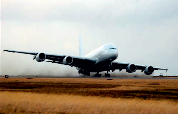
Figure 1 Take-off from Keflavik, Iceland. Note how the wind lifts the right wing. Maximum reported crosswind at the time was 56 kt in gusts
Extract from A330/A340 FCTM information on take-off roll (all Airbus programs share the same philosophy):
For crosswind take-offs, routine use of into wind aileron is not recommended. In strong crosswind conditions, small amounts of lateral control may be used to maintain wings level, but the pilot should avoid using excessive amounts. This causes excessive spoiler deployment, which increases the aircraft’s tendency to turn into wind, reduces lift, and increases drag. Spoiler deflection starts to become significant with more than half side stick deflection. As the aircraft lifts off, any lateral control applied will result in a roll rate demand. The objective is for the wings to be maintained level.
This philosophy applies to the entire Airbus fleet. Although the lateral stick displacement threshold for spoiler deployment varies a little between types, the objective of avoiding unnecessary spoiler deployment however remains valid.
Safety
6. Landing Technique
Section titled “6. Landing Technique”The wings level technique is recommended. In particularly strong crosswinds kicking off around two third drift as a minimum is normally sufficient to ensure that the lateral stresses are not excessive on the undercarriage at touchdown (max residual drift 5 deg at touchdown), whilst at the same time ensuring minimum risk of a downwind drift away from the runway centreline. This has been applied to all aircraft from the A300/310, where roll/yaw coupling during
decrab is marked due to the wingsweep/dihedral effect, through the single aisle and long range Fly By Wire (FBW) aircraft where lateral compensation is similarly required and to the A380 where flight control law compensation provides a pure yaw response to rudder pedal input.
Where small amounts of lateral control are eventually required, avoid excessive bank angles (max bank angle 5 deg). Aim for a positive touchdown and do not be tempted to finesse the touchdown or float for any considerable time. This will inevitably lead to a downwind drift away from the centreline.
For the A380, and in the near future for the A350 XWB, there is no apparent induced roll when kicking off drift in the flare due to flight control law compensation. The flare laws in these two types have been adapted to produce a pure yaw demand when applying rudder to reduce drift prior to touchdown. Of course, the flight control surfaces are providing the lateral input for you, behind the scenes, in order to prevent the natural lateral stability of the aircraft from producing the induced rolling effect. However, this is transparent to the pilot who is looking down the runway to ensure he lands his aircraft in the right place without excessive drift.
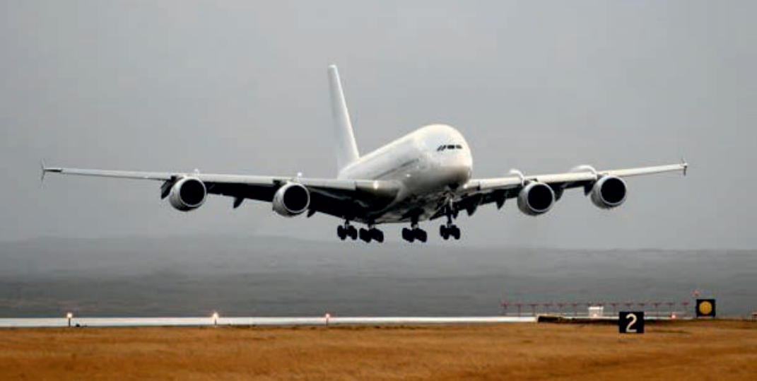
Figure 2
Section titled “Figure 2”Extract from A380 FCTM information on lateral and directional control (all Airbus programs share the same philosophy):
“Crabbed” final approach to Keflavik, Iceland. Picture taken from the south taxiway with the runway easily visible. Maximum reported crosswind at the time was 56 kt in gusts
FINAL APPRoACH
Section titled “FINAL APPRoACH”In crosswind conditions, the flight crew should fly a “crabbed” final approach wings level, with the aircraft (cockpit) positioned on the extended runway centerline until the flare.
The objectives of the lateral and directional control of the aircraft during the flare are:
-
To land on the centerline
-
To minimize the loads on the main landing gear.
The recommended de-crab technique is to use the following:
-
The rudder to align the aircraft with the runway heading during the flare
-
The roll control, if needed, to maintain the aircraft on the runway centerline.
The flight crew should counteract any tendency to drift downwind by an appropriate lateral(roll) input on the sidestick.
In the case of strong crosswind during the de-crab phase, the PF should be prepared to add small bank angle into the wind to maintain the aircraft on the runway centerline. The flight crew can land the aircraft with a partial de-crab (i.e. a residual crab angle up to about 5 deg) to prevent an excessive bank. This technique prevents wing tip or engine nacelle strike caused by an excessive bank angle. Therefore it is wise to know what the maximum bank angle is during the flare phase for the type you are flying so as to ensure no such strikes. As a consequence, this can result in touching down with some bank angle into the wind, therefore, with the upwind landing gear first.
One further point is worth mentioning, because we see repeated cases in Flight Operational Quality Assurance (FOQA) data in which less than optimum crosswind touchdowns are made: the response to rudder pedal input at the decrab is positive for all our aircraft. However, due to pure aerodynamics and inertia it takes a reasonable time from the input being made to the aircraft reacting. If we were hand-flying in crosswinds every day, we would become very well tuned to the aircraft response and make a perfect crosswind landing every time (I wish!). However, there appears to be a tendency, borne out by operational Digital Flight Data Recorder (DFDR) data, towards a late initiation of the decrab. This is perhaps natural, since the risks associated with an early decrab are perhaps more severe. However, practice, as always, is the key. Any opportunity in the simulator, even if not truly representative of the flying the real aircraft is invaluable, as the response time to rudder input should be representative.
7. Effect of Thrust Reverse
Section titled “7. Effect of Thrust Reverse”Of course, touchdown is not the complete story, as the roll-out is an equally important phase of the crosswind landing. This is where ground based dynamics come into play, even though there are still varying degrees of aerodynamic controllability during the deceleration phase.
When selecting reverse thrust with a given crab angle, the reverse thrust results into two force components:
-
q A stopping force aligned along the aircraft direction of travel (runway centerline)
-
q A side force, perpendicular to the runway centerline, which further increases the tendency to skid sideways.
Unequal weight distribution on the main landing gear during touchdown and braking also produces a yawing moment. This can be destabilizing should the asymmetric
wheel loading and braking be sufficiently high and this can be caused by the crosswind itself or by lateral stick input. Furthermore, autobrake systems do not always provide a useful aid in this regard, as they will apply braking regardless of whether one main-wheel bogie alone has released brake pressure due to antiskid operation.
In all cases, brakes and reverse should be applied smoothly. If there is any concern with directional controllability then reduce or cancel reverse as necessary and reduce braking until control is regained. Then smoothly re-apply brakes and reverse if necessary.
8. Operational Implications
Section titled “8. Operational Implications”With the FCOM provided maximum demonstrated crosswind value and the tower provided current wind value, the decision making process is not always easy for the pilot on approach in limiting wind conditions. Runway condition is also a factor critical to maintaining lateral control once on the ground and has to be considered. Companies may provide operation recommendations, but the topography around the touchdown zone can sometimes lead to significant variations of actual winds experienced. Local knowledge is very useful and often incorporated in specific airfield briefs. It is perhaps natural, therefore, that many pilots glance at the ND windspeed indication during approach to help them in their decision making process. There is a catch here, how-
10. Conclusion
Section titled “10. Conclusion”The maximum demonstrated crosswind is just that: a demonstrated value that was observed during certification based upon the weather conditions that we were able to find during the flight test campaign. Companies may define their own limitations based upon their own experience. For the line Captain, asking himself whether he can land or take-off in the crosswind condi-
ever. As ND wind on A320 Family/A330/A340 is derived from IRS data, indications may be significantly different from reality. This is due to the lack of correction for the IRS drift, mentioned earlier. On A380 (and in the future for A350 XWB), the use of GPS Ground Speed for the ND wind display provides a more reliable additional source of information. Ultimately, it is the Captain who is called upon to use his judgement and skill, based upon all the data and knowledge available to him.
Remember also that if your aircraft has a degraded flight control system through MEL clearance or in flight failure, then a more severe crosswind limitation may apply. Similarly, an engine out condition will imply a limited ability to correct for drift in one direction. Again a more restrictive limitation may exist.
9. Autoland Certification
Section titled “9. Autoland Certification”Certification of autoland and its associated wind limitations is done based upon a statistical analysis of autolands carried out during flight test and certification. These values should be treated as hard limits for the autoland system. Although, in theory, if the tower winds indicate that you are within the autoland crosswind limit you can continue to make your autoland, common sense would indicate that you take care, as in reality the winds could be beyond the autoland system capability. As always, be ever ready to take over manually should the need occur.
tions of the day, he should take all information available to him in the decision making process. Tower wind may be the starting point, but it is not the whole story. Ultimately the responsibility rests with the Captain and if there is any doubt, discontinue the approach. As always, the anticipation of what is coming is the key to a successful outcome.
Safety
安全
弗兰克·查普曼(Frank CHAPMAN)
Section titled “弗兰克·查普曼(Frank CHAPMAN)”试飞员
本文是空客系列文章之一,旨在跨越制造企业认证领域与航空公司日常运行环境之间的信息鸿沟。
乍一看,大型运输类飞机的侧风取证问题似乎很简单。以下是 EASA CS25.237(a) 要求的节选:
必须建立 90 度侧风分量速度,经证明在干跑道起飞和着陆时是安全的,且至少为 20 节或 Vs MLW(最大着陆重量下 1g 失速速度)中的较大值,但无需超过 25 节。
然而,该主题远比这句简短的话所能引导您相信的要复杂得多。那么,在飞行试验和取证过程中我们如何处理侧风?这对航空公司又意味着什么?
历史上,有两种计算方法。早期的取证工作使用空管塔台的风数据来评估飞行试验机组在起飞和着陆时经历的侧风等级。这是通过一种老式的风速计记录系统完成的,在名义上距地面 10 米高度处记录风值。这种方法逐步演变为使用飞机生成的侧风数据,即在起飞和着陆前后约 20 秒(±10 秒)的时间段内,通过真实空速(TAS)矢量与惯性基准系统(IRS)计算的地速(GS)矢量之差来计算 10 米高度的风速。然而,由于 IRS 固有的漂移会产生误差,必须考虑这一点。漂移值必须定期测量,以便修正 IRS 地速。随着差分 GPS(DGPS)和更新的机载仪器系统的出现,GS 矢量现在使用高精度数据计算,因此不再需要这种修正。
在取证早期,使用塔台风时,平均风值取自前两分钟,阵风值取自前 10 分钟时段。尽管国际民航组织(ICAO)仅在峰值超过两分钟平均值 10 节以上时才考虑阵风,但一些机场气象服务提供的阵风值低于 10 节。这种方法至今仍用于空管塔台风的广播播报。然而,使用新的飞行试验方法,对飞机能力的评估要更具代表性。
在早期空客取证时,我们在飞行手册(FCOM)中提供”平均风加阵风”值。然而,许多人认为这种格式使决策过程复杂化。因此,从 2004 年开始经过一段时间的研究后,我们现已改为”单一数值,含阵风”。这意味着可以直接将(我们制造商提供的)最大演示值与塔台或自动终端情报服务(ATIS)通报的最大值(包括通报的阵风)进行比较。
3. 最大演示侧风定义
Section titled “3. 最大演示侧风定义”如今,飞行手册(FCOM)中的最大演示侧风来源于在整个取证过程中遭遇的最大侧风,并以与相关部门商定的方式记录。这不一定是飞机的最大侧风能力。它纯粹基于取证期间在飞机上记录的数据。此外,众所周知它经常与空管提供的风数据存在显著差异。
4. 飞行试验方法
Section titled “4. 飞行试验方法”首先,在起飞或着陆前后 ±10 秒的时间段内收集飞机所经历的风数据。然后,我们需要将这些数据与已建立的 10 米基准高度相关联。这是通过对数据进行数学修正来完成的,修正值随高度变化,以补偿近地面的边界层类型效应。
然后,将观测到的阵风的一个保守比例加到所获得的最大稳定侧风值上。凭借这个(加了阵风的)值,我们根据经验性的飞控响应数据,检查在等效稳定风情况下是否具有足够的控制权限。如果这得到验证,我们向相关部门提议该值用于取证,并将其纳入飞机飞行手册(AFM),分别针对起飞和着陆。
然而,在起飞时,还有另一个可能对侧风限制和/或起飞程序产生重大影响的因素:发动机进气气流畸变。这在单独的分析中论述,并进行了许多试验以确保我们在起飞和着陆期间为发动机提供合适的工作包线。然而,这可能会影响所提供演示侧风值的最终选择,并且几乎肯定会影响应用起飞功率的程序。制造商可以选择在某些地速下自动限制发动机状态,类似于他们有时自动避开某些转速范围以避免风扇叶片颤振的方式。然而,总会有轻微的折衷,以确保起飞性能不会因此显著降低。对于 A380 和 A340-500/600 等机型施加了限制,其中发动机限制比演示侧风限制更严格,这部分内容已在飞行手册(FCOM)的限制部分公布。
5. 起飞技术
Section titled “5. 起飞技术”发动机设计选择是确定起飞推力初始程序方法的重要因素,如上所述,交叉风可能是限制因素。在滑跑阶段应避免大量使用横侧控制,以防止扰流板的伸出,这将对性能产生不利影响,并可能引起方向扰动。在强交叉风条件下,飞机在离地时会有自然地向下风侧滚转的趋势,可以通过在飞机起飞时平滑地输入横侧控制来补偿。
图 1 冰岛凯夫拉维克起飞。注意风如何抬起右机翼。当时报告的最大阵风侧风为 56 节
摘自 A330/A340 FCTM 关于起飞滑跑的资料(所有空客项目均遵循相同的理念):
对于交叉风起飞,不建议常规使用迎风侧的副翼。在强交叉风条件下,可使用少量横侧控制来保持机翼水平,但飞行员应避免过量使用。这会导致扰流板过度伸出,增加飞机向迎风方向偏转的趋势,减少升力并增加阻力。当侧杆偏转超过一半时,扰流板的偏转开始变得显著。当飞机离地时,任何应用的横侧控制都会产生滚转率需求。目标是保持机翼水平。
该理念适用于整个空客机队。尽管不同型号横侧杆位移触发扰流板展开的阈值略有不同,但避免不必要扰流板展开的目标保持不变。
6. 着陆技术
Section titled “6. 着陆技术”建议采用机翼水平技术。在特别强的交叉风条件下,以至少约三分之二的偏流角进行蹬舵消除偏流,通常足以确保接地时起落架上的侧向载荷不会过大(接地时最大残余偏流角为 5 度),同时确保飞机偏离跑道中心线向下风侧漂移的风险最小。这一方法已应用于从 A300/310(由于机翼后掠角/上反角效应,消除偏流时的滚转/偏航耦合明显)到单通道和远程电传飞行(FBW)飞机(同样需要横侧补偿),再到 A380(其飞行控制律补偿提供对方向舵脚蹬输入的纯航向响应)的所有机型。
当最终需要少量横侧控制时,应避免过大的坡度角(最大坡度角 5 度)。目标是实现稳定的接地,不要试图精细调整接地或在空中飘荡过久。这将不可避免地导致飞机偏离跑道中心线向下风侧漂移。
对于 A380,以及即将投入使用的 A350 XWB,由于飞行控制律的补偿,在拉平阶段蹬舵消除偏流时不会产生明显的诱导滚转。这两种机型的拉平法则已做适配,在接地前使用方向舵消除偏流时会产生纯航向需求。当然,飞行控制面在后台为您提供横侧输入,以防止飞机自然的横侧稳定性产生诱导滚转效应。然而,这对飞行员来说是透明的——飞行员只需要看着跑道,确保在正确的位置着陆,不要有过大的偏流角。
从 A380 FCTM 中摘录的侧向和方向控制信息(所有空客项目遵循相同理念):
“偏流”方式执行雷克雅未克(冰岛)最后进近。照片从南滑行道拍摄,跑道清晰可见。当时报告的最大侧风为阵风56节。
在侧风条件下,飞行机组应采用”偏流”方式执行最后进近,保持机翼水平,将飞机(驾驶舱)对正跑道中心线延长线,直至拉平。
拉平阶段侧向和方向控制的目标如下:
- 在跑道中心线上接地
- 尽量减少主起落架的载荷
推荐的消偏流(de-crab)技术如下:
- 在拉平阶段使用方向舵使飞机对准跑道方向
- 如有需要,使用横滚控制将飞机保持在跑道中心线上
飞行机组应通过适当的侧向(横滚)输入来抵消任何向下风方向漂移的趋势。
在消偏流阶段遇到强侧风时,PF 应准备好向风侧增加小的坡度角,以将飞机保持在跑道中心线上。飞行机组可以采用部分消偏流的方式着陆(即保留约5度以内的残余偏流角),以防止过大的坡度角。此技术可防止因坡度过大而导致翼尖或发动机吊舱触地。因此,有必要了解所飞机型在拉平阶段的最大允许坡度角,以确保不发生此类碰撞。由此,可能导致飞机带着向风侧的一定坡度角接地,因此前起落架(接地端)先触地。
还有一点值得注意,我们在飞行运行质量保证(FOQA)数据中看到多次最佳侧风接地未达最优的情况:在消偏流时方向舵脚蹬输入的响应在所有机型上都是正向的。然而,由于纯空气动力学原理和惯性,从输入到飞机响应需要相当的时间。如果我们每天都在侧风中手动飞行,我们会变得非常适应飞机的响应,每一次都能做出完美的侧风着陆(我希望如此!)。然而,根据运行数字式飞行数据记录器(DFDR)数据,似乎存在消偏流启动过晚的趋势。这也许是自然现象,因为过早消偏流的相关风险可能更严重。然而,一如既往,练习是关键。任何在模拟机上的练习机会,即使不能完全真实地代表实际飞行,也是非常宝贵的,因为方向舵输入的响应时间是具有代表性的。
7. 反推的影响
Section titled “7. 反推的影响”当然,接地并不是完整的故事,滑跑是侧风着陆同样重要的阶段。此时地面动力学开始发挥作用,尽管在减速阶段仍存在不同程度的空气动力可控性。
当以给定的偏流角选择反推时,反推产生两个分力:
- 沿飞机行驶方向(跑道中心线)的制动减速力
- 垂直于跑道中心线的侧向力,进一步增加侧向滑移的趋势
在接地和刹车过程中,主起落架上的不均匀重量分布也会产生偏航力矩。如果非对称的轮载和刹车足够大,这可能会造成不稳定,而这种不对称可能由侧风本身或侧向杆输入引起。此外,自刹车系统并不总能在这一方面提供有用的帮助,因为无论一个主轮转向架是否因防滑操作而释放刹车压力,自刹车都会施加刹车力。
在任何情况下,刹车和反推都应平稳施加。如对方向可控性有任何担忧,应按需减少或取消反推,并减少刹车直至重新获得控制。然后如有需要,平稳地重新施加刹车和反推。
8. 运行影响
Section titled “8. 运行影响”凭借 FCOM 中提供的最大演示侧风值和塔台提供的当前风值,飞行员在限制侧风条件下进近时的决策过程并非总是一帆风顺。跑道状况也是地面阶段保持侧向控制的关键因素,必须加以考虑。公司可提供运行建议,但接地区周围的地形有时会导致实际遭遇的侧风出现显著变化。本地知识非常有用,通常会被纳入特定的机场简令。因此,许多飞行员在进近时浏览 ND 风速显示以辅助决策,这或许是很自然的行为。然而需要注意的是…
10. 结论
Section titled “10. 结论”最大演示侧风就是其字面含义:这是一个基于我们在飞行试验期间能够找到的气象条件,在审定过程中观测到的演示值。各公司可根据自身经验定义自己的限制值。对于航线机长而言,在决定是否能够在当日的侧风条件下起飞或着陆时,应在决策过程中综合考虑所有可用信息。塔台风可能是一个起点,但并非全部。最终,责任由机长承担,如有疑问,应中断进近。和往常一样,对即将出现情况的预判是成功着陆的关键。
9. 自动着陆审定
Section titled “9. 自动着陆审定”自动着陆及其相关侧风限制的审定,是基于对飞行试验和审定期间执行的自动着陆进行统计分析完成的。这些值应被视为自动着陆系统的硬性限制。虽然理论上如果塔台风表明你在自动着陆侧风限制范围内,你可以继续执行自动着陆,但常理表明你应保持警惕,因为实际侧风可能已超出自动着陆系统的能力。与往常一样,随时准备在需要时进行手动接管。
Safety