Near CFIT event during Non Precision Approach
Source: Airbus Safety First URL: https://safetyfirst.airbus.com/near-cfit-event-during-non-precision-approach/ Published: 2007-12-15 Magazine Issue: 2007-12 Category: Archive PDF: Original PDF
of fog closing and opening the station. On final approach, due to low visibility, the crew initiated a go-around and hit electrical lines. The crew then diverted to the scheduled alternate airport.”
By: Panxika Charalambides Flight Safety Manager
The investigation performed on site revealed that 25ft high electrical lines, located perpendicularly to the runway axis, at about 1100m from the runway threshold, were found sheared.
1 Introduction
Section titled “1 Introduction”The aircraft was damaged subsequently to the impact with the electrical power lines. Damage was present all across the aircraft (fuselage, engine, wings) indicating that the aircraft impacted the lines head-on. Furthermore, some pieces of electrical lines were found in the area of the nose landing gear and it was concluded that the initial impact occurred at nose landing gear level.
Today most of major incidents and accidents belong to one of the following categories: • Controlled Flight Into Terrain (CFIT)
-
Loss of control in flight
-
Landing short
-
Runway excursion
In particular CFIT events make up 45% of approachand-landing accidents, that represent 55% of global accidents.
The aircraft diverted and landed at the scheduled alternate airport. There were no passenger or crew injuries during this incident.
This article details a near CFIT event encountered on a single aisle aircraft as well as the associated lessons learned.
This article is mainly based on the analysis of the DFDR, which was provided to Airbus. Human factors aspects, in particular, will not be covered, due to lack of information.
This event presents numerous classical components conducive to a CFIT and approach accident.
2 Re orted event p
Section titled “2 Re orted event p”3 DFDR anal sis y
Section titled “3 DFDR anal sis y”The following was reported to Airbus: “This flight was uneventful until the approach phase that was a non precision approach performed in VMC conditions. Weather report indicated a partly cloudy sky with 10 miles visibility at destination, but, during the descent, ATC informed the crew about variable weather conditions due to banks
Note: for de-identification reasons altitudes are given in heights with reference to QFE.
This was a step-down VOR-DME approach conduc ted in daylight, early in the morning, autopilot engaged.
Descent profile
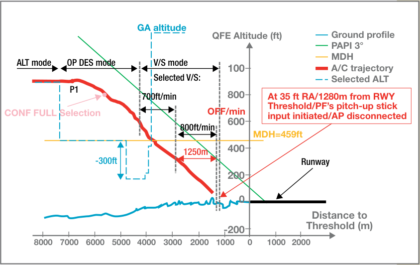
As a consequence, the approach was a succession of descent and level flight phases so that autopilot longitudinal modes were alternatively OP DES mode and ALT*/ALT modes, while the auto-thrust modes were respectively idle mode and speed mode (with speed managed by the FMS). The successive constraint altitudes were fully respected. Shortly before over-flying the last altitude constraint “P1” (859ft QFE situated at 3.7NM from the runway threshold) the aircraft was in level flight at 860ft QFE. The minimum descent height was 459ft.
-
While descending below MDA about 2.1 NM from runway threshold, go-around altitude was selected on the FCU.
-
At 325ft QFE/ 1.54NM from runway threshold, the crew selected a vertical speed of - 800ft/min.
-
At 47ft RA at about 0.72NM from runway threshold the crew selected a vertical speed of 0ft/min.
-
At 35ft RA, at 0.70 NM from runway threshold, the Pilot Flying applied 2/3 of full back stick input that disconnected immediately the autopilot.
The figure here below presents the descent profile from “P1”
Section titled “The figure here below presents the descent profile from “P1””This sequence can be detailed as follows:
- Shortly before overflying “P1”, MDA altitude was selected on the FCU, and the OP DES longitudinal autopilot mode was selected so that a thrust reduction was progressively commanded to target idle thrust, while the autopilot pitch mode maintained the speed target.
- For the whole approach the autopilot lateral mode remained in NAV mode.
Notes:
Section titled “Notes:”-
1/ As this approach was performed in GPS primary (In this case only GPS and IRS data are used for the aircraft position computation) the accuracy of the recorded aircraft position is very good.
-
At 800ft QFE, 3NM from runway threshold, shortly after over-flying the last altitude constraint “P1” full slats/flaps configuration was selected.
-
• At 680ft QFE, 2.6NM from runway threshold, whereas the rate of descent was 1000ft/min, an altitude 300ft below MDA was selected on the FCU.
-
2/ In managed guidance only (FINAL APP mode engaged) when the aircraft reaches MDA (MDH) –50ft or 400ft (if no MDA/MDH entered) the autopilot automatically disengages.
-
At 600ft QFE, 2.3NM from runway threshold, while the current rate of descent was -1400ft/min, the crew selected the autopilot V/S mode with initially a selected V/S of -700ft/min. From that time auto-thrust was therefore engaged in speed mode. Target speed was Vapp (VLS +5kts).
-
3/ As noticeable on the figure here above, from MDA altitude this final descent was performed on a 3° slope.
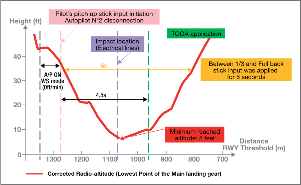
The figure here below presents a zoom on the pilot’s take-over phase:
-
The radio-altimeter parameters recorded in the DFDR (here plotted in red ) indicate the distance between the lowest point of the main landing gear and the ground.
-
The initial PF’s pitch-up stick input was followed by permanent pitch-up stick input (between 1/3 and full back stick input) applied for 6 seconds, so that the aircraft stopped descending and started to climb.
-
Minimum recorded altitude was 5ft RA reached at about 1100m from the runway threshold.
-
The estimation of the impact location indicates that, at that moment, the aircraft impacted the electrical lines.
-
At 10ft RA, 4.5 seconds after the initial PF’s pitchup stick input, thrust levers were moved forward to TOGA detent.
-
43 seconds after TOGA application, landing gears were selected up.
-
2 minutes after TOGA application, Slats/Flaps configuration 3 was selected.
-
The aircraft diverted to the scheduled alternate airport.
4 Lessons learned
Section titled “4 Lessons learned”Following are the lessons to be learned from this near CFIT event:
4.1 Descent below MDA requests adequate visual references:
Section titled “4.1 Descent below MDA requests adequate visual references:”When conducting a non precision approach, it is recommended to apply the “Non Precision Approach” Standard Operating Procedures. In particular, when the aircraft is properly established at MDA, the runway in sight must be confirmed by both PF/PNF, before disconnecting the autopilot and descending for a visual approach.
Furthermore, if the required visual references are met at MDA but are lost at any time below MDA, a go-around procedure must be immediately applied.
This is also highlighted in Chapter 7.3 (Acquisition of visual references) of the “Getting to Grips with…” ALAR brochure (Approach And Landing Accident Reduction).
This brochure can be downloaded from the Flight Operations Community at https://w3.airbus.com/.
4.2 Parameters monitoring
Section titled “4.2 Parameters monitoring”When conducting this particular approach, successive radio-altimeter callouts triggered below 200ft RA, while the aircraft was getting closer and closer to the ground, should have alerted the crew.
It is recommended as soon as the radio-altimeter is activated (at 2,500 feet AGL) to call out “radio altimeter alive”. The radio altimeter reading should then be included in the instrument scanning for the remainder of the approach. See Flight Operations Briefing Note “ Altimeter Setting – Use of Radio Altimeter.”
4.3 Step-down Non Precision Approach:
Section titled “4.3 Step-down Non Precision Approach:”For non precision approaches, Airbus recommends implementing the Constant Angle Non Precision Approach (CANPA) rather than the classical stepdown non precision approach. Flying a constantangle approach profile will reduce the risk of CFIT. Indeed it will provide a more stabilized flight path, will reduce the workload during this critical flight phase and will minimize the risk of error in stepdown distances/altitudes and the need for a level off at the MDA (MDH). This technique is detailed in the chapter 7.2 (Flying Constant-Angle Non Precision Approaches) of the “Getting to Grips with…” ALAR brochure (Approach And Landing Accident Reduction).
- 4.4 No EGPWS alert was triggered during the flight phase where the aircraft was getting very close to the ground:
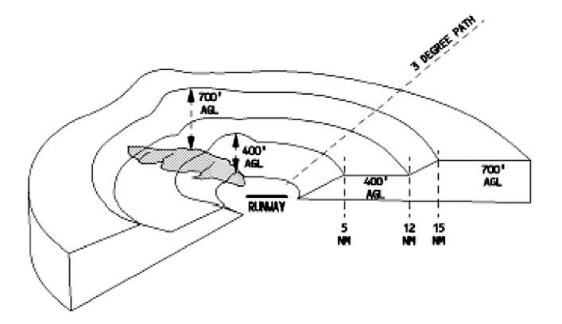
As the aircraft was in landing configuration (full slats/ flaps, gear down…) no GPWS (Ground Proximity Warning System) basic modes could have been triggered, but as the aircraft was fitted with an E(enhanced)GPWS, the EGPWS mode “Terrain Clearance Floor (TCF) ” could have been triggered. Indeed, the TCF function uses a Terrain Clearance Floor envelope (see drawing here below) stored in the EGPWS database for each runway for which terrain data exists, and warns in case of premature descent below this floor, regardless of the aircraft configuration.
If the aircraft descends below this floor a “TOO LOW TERRAIN” aural warning sounds. In case of such alert, it is recommended by the Standard Operating Procedures (SOPs) either to adjust the flight path (In daylight with terrain and obstacles clearly in sight) or to initiate an immediate goaround (during night or IMC conditions).
This FOBN can be downloaded from the Flight Operations Community at https://w3.airbus.com/.
But as shown on the sketch here below there is a progressive desensitization of this function when the aircraft approaches the runway. In particular, in a circle centered on the runway, a full desensitization exists i.e. no warning when the aircraft is very close to the runway. With the EGPWS software version fitted on this particular aircraft, the Terrain Clearance Floor function had a higher desensitization zone than current EGPWS, so that no alert was given when the aircraft descended very close to the ground. With the latest EGPWS software version (the aircraft was equipped with a GPS), an alert would have been triggered about 20s before impacting the electrical lines (at about 200ft QFE).
- Note: The desensitization area depends on the FMS estimated position accuracy. In particular this software release allows for the GPS position data to be used directly, resulting in much smaller estimated error values that allow for smaller desensitization areas. This latest software version was revised to optimize the envelope profile and to reduce the minimum desensitization area to a circle with a radius of 0.25NM, whereas such radius was 1NM for the software version installed on the aircraft at the time of the event. This results in significantly improved protection for “landing short” accidents.
Upgrade to last EGPWS software standard (P/N 965-1676-002) for any Airbus aircraft type: Please refer to OIT ref. SE 999.0050/06/VHR dated 18 April 2006. Please refer to last ref. SIL 34-080 revision
This last, free of charge, EGPWS software version is available for any Airbus aircraft type since May 2006.
4.5 MDA and then an altitude lower than MDA were successively selected on the FCU during the final approach:
Section titled “4.5 MDA and then an altitude lower than MDA were successively selected on the FCU during the final approach:”When performing non precision approaches, Airbus does not recommend MDA selection and even less so an altitude below MDA. Indeed, this may cause unwanted ALT* mode engagement and consequently approach destabilization at a critical stage of the approach. Therefore FCU altitude should be set at go-around altitude after over-flying the final approach fix (FAF).
5 Conclusion
Section titled “5 Conclusion”Five main recommendations should be particularly highlighted:
-
To be go-around prepared and go-around minded When performing an approach, even and because the go-around is not a frequent occurrence, it is of prime importance to always be go-around-prepared and go-around-minded. This will help in performing the go-around appropriately, in the optimal conditions and as per procedures.
-
To adhere strictly to SOPs for Non Precision Approaches In particular altitude/distance checks and respect of MDA are crucial when performing Non Precision Approaches.
-
To retrofit a GPS on aircraft not already equipped with this system The installation of a GPS improves the efficiency of the EGPWS by providing a more accurate aircraft position to the system.
-
To upgrade the EGPWS software standard The EGPWS software should be upgraded with the last version (free of charge for any Airbus aircraft type), which reduces the desensitization area.
-
Constant Angle Non Precision Approach Airbus encourage the operators to work with their Authorities in order to translate step down Non Precision Approaches into Constant Angle Non precision Approaches.
In particular the flight crew should have a clear view of excessive deviation and should be ready to interrupt the approach if:
-
Ceiling and visibility are below the required weather minimums
-
Criterias for stabilized approach are not achieved
-
Doubt exists about the aircraft position
-
There is confusion about the use of automation
-
The aircraft is destabilized below MDA
-
The visibility is lost below MDA
在非精密进近过程中险些发生可控飞行撞地(CFIT)事件
浓雾时开时闭,飞机在最后进近时由于能见度低,机组执行了复飞并撞上了电线。随后机组备降至预定的备降场。
作者:Panxika Charalambides 飞行安全经理
现场调查表明,位于跑道延长线垂直方向、距跑道入口约1100米处、高25英尺的电线被切断。
飞机在与电线碰撞后受损。损坏分布于整个机体(机身、发动机、机翼),表明飞机正面撞上了电线。此外,在前起落架区域发现了一些电线残骸,由此判断初始碰撞点位于前起落架高度。
如今,大多数重大事故征候和事故属于以下类别之一:
- 可控飞行撞地(CFIT)
- 飞行中失去控制
- 着陆距离不足
- 跑道冲出
其中,CFIT 事件占进近和着陆事故的45%,而进近和着陆事故占全球事故总量的55%。
飞机备降后在预定备降场落地。此次事件中,旅客和机组人员均未受伤。
本文详细描述了一起在单通道飞机上险些发生的 CFIT 事件及相关经验教训。
本文主要基于空中客车公司收到的 DFDR(数字式飞行数据记录器)数据分析。由于信息有限,文中将不涉及人为因素方面的内容。
该事件包含了许多导致 CFIT 和进近事故的典型因素。
2 报告的事件
Section titled “2 报告的事件”3 DFDR 分析
Section titled “3 DFDR 分析”以下内容已向空中客车公司报告:“此次飞行在进近阶段之前一切正常,进近为在目视气象条件下执行的非精密进近。目的地天气报告为少云,能见度10英里。但在下降过程中,空中交通管制通知机组,由于雾带的影响,天气条件多变。”
注:出于去识别化原因,高度以相对于 QFE 的高度形式给出。
这是一次阶梯式下降的 VOR-DME 进近,在清晨白天进行,自动驾驶仪接通。
下降剖面
因此,进近过程由一连串的下降和平飞阶段组成,自动驾驶仪的俯仰模式在 OP DES 模式和 ALT*/ALT 模式之间交替,自动推力的模式分别为怠速模式和速度模式(速度由 FMS 管理)。各阶梯约束高度均被严格执行。在飞越最后一个高度约束点“P1”(QFE 859英尺,距跑道入口3.7海里)前不久,飞机在 QFE 860英尺高度平飞。最低下降高度为459英尺。
- 在距跑道入口约2.1海里、高度降至 MDA 以下时,机组在 FCU 上选择了复飞高度。
- 在 QFE 325英尺/距跑道入口1.54海里处,机组选择了-800英尺/分钟的下降率。
- 在无线电高度47英尺、距跑道入口约0.72海里处,机组选择了0英尺/分钟的下降率。
- 在无线电高度35英尺、距跑道入口0.70海里处,操纵飞行员施加了约2/3的全向后杆输入量,自动驾驶仪随即断开。
下图展示了从”P1”开始的下降剖面
Section titled “下图展示了从”P1”开始的下降剖面”该过程可详述如下:
- 在飞越”P1”前不久,在FCU上选择了MDA高度,并选择了OP DES纵向自动驾驶模式,以逐步指令推力减小至目标慢车推力,同时自动驾驶俯仰模式保持速度目标。
- 在整个进近过程中,自动驾驶横向模式保持在NAV模式。
-
1/ 由于此次进近以GPS主用模式执行(此时仅使用GPS和IRS数据进行飞机位置计算),记录飞机位置的精度非常高。
-
在800ft QFE,距跑道入口3NM处,飞越最后高度限制点”P1”后,选择了全缝翼/襟翼构型。
-
在680ft QFE,距跑道入口2.6NM处,当下降率为1000ft/min时,在FCU上选择了低于MDA 300ft的高度。
-
2/ 仅在机动引导模式(FINAL APP模式接通)下,当飞机到达MDA(MDH)-50ft或400ft(如未输入MDA/MDH)时,自动驾驶自动断开。
-
在600ft QFE,距跑道入口2.3NM处,当当前下降率为-1400ft/min时,机组在自动驾驶V/S模式下初始选择了-700ft/min的V/S。从此时起,自动推力以速度模式接通。目标速度为Vapp(VLS +5kts)。
-
3/ 如上图所示,从MDA高度开始,最后下降以3°坡度进行。
下图展示了飞行员接管阶段的放大视图:
-
DFDR中记录的无线电高度参数(图中红色绘制)表示主起落架最低点与地面之间的距离。
-
初始PF的俯仰向上杆输入之后是持续的俯仰向上杆输入(在1/3至全后杆输入之间),持续6秒,使飞机停止下降并开始上升。
-
记录的最低高度为距跑道入口约1100m处的5ft RA。
-
着陆位置估算表明,在该时刻,飞机撞击了电力线。
-
在10ft RA处,初始PF俯仰向上杆输入后4.5秒,推力手柄移至TOGA卡位。
-
TOGA应用后43秒,起落架收起。
-
TOGA应用后2分钟,选择缝翼/襟翼构型3。
-
飞机备降至预定备降场。
4 经验教训
Section titled “4 经验教训”以下是从本次近CFIT事件中应汲取的经验教训:
4.1 低于MDA下降需要适当的目视参考:
Section titled “4.1 低于MDA下降需要适当的目视参考:”进行非精密进近时,建议执行”非精密进近”标准操作程序。特别是在飞机正确地在MDA建立后,必须由PF/PNF双方确认看到跑道,才能断开自动驾驶并下降进行目视进近。
此外,如果在MDA获得了所需的目视参考,但在MDA以下的任何时候失去,必须立即执行复飞程序。
《减少进近和着陆事故》(ALAR)手册第7.3章(获取目视参考)中也对此进行了强调。
该手册可从飞行运营社区网站下载:https://w3.airbus.com/。
4.2 参数监控
Section titled “4.2 参数监控”进行此项特殊进近时,在低于200ft RA时连续触发无线电高度计报告,而飞机离地面越来越近,这应该引起机组的警觉。
建议在无线电高度计激活时(AGL 2,500英尺)报告”无线电高度计工作”。无线电高度计读数应包含在进近剩余阶段的仪表扫视中。参见飞行运营简报”高度表设置——无线电高度计的使用”。
4.3 分阶段非精密进近:
Section titled “4.3 分阶段非精密进近:”对于非精密进近,空客建议采用恒定角度非精密进近(CANPA),而非传统的分阶段非精密进近。保持恒定角度进近剖面可降低可控撞地(CFIT)风险。这是因为恒定角度进近能够提供更加稳定的航迹,减少该关键飞行阶段的工作负荷,并最大限度降低分阶段距离/高度差错以及在最低下降高度(MDA/MDH)需要平飞的风险。该技术详见《避免进近着陆事故》(ALAR)手册第7.2章(实施恒定角度非精密进近)。
- 4.4 在飞机非常接近地面的飞行阶段,未触发EGPWS警告:
由于飞机处于着陆构型(缝翼/襟翼全放出,起落架放下……),基本GPWS(地面接近警告系统)模式无法被触发,但由于该飞机配备了增强型(E)GPWS,增强型EGPWS的”地形净空高度(TCF)“模式本应能够被触发。TCF功能使用存储在EGPWS数据库中针对每条有地形数据的跑道生成的地形净空高度包线(见下图),无论飞机构型如何,在提前下降至该净空高度以下时发出警告。
如果飞机下降至该净空高度以下,“TOO LOW TERRAIN”(地形过低)语音警告会响起。标准操作程序(SOPs)建议:遇到此类警告时,要么调整航迹(在昼间且能清楚看到地形和障碍物时),要么立即执行复飞(在夜间或仪表气象条件下)。
此FOBN可从Flight Operations Community下载,网址为 https://w3.airbus.com/。
但如下图所示,当飞机接近跑道时,此功能会逐渐降低灵敏度。特别是以跑道为中心的圆范围内,存在完全失效区,即当飞机非常接近跑道时不会触发任何警告。由于该飞机所装的EGPWS软件版本的地形净空高度功能失效区比当前EGPWS更大,因此当飞机下降到非常接近地面时未发出任何警告。安装最新版本EGPWS软件后(该飞机配备了GPS),在大约撞击电线前20秒左右就会触发警告(高度约为200ft QFE)。
- 注:失效区取决于FMS估算的位置精度。特别是该软件版本允许直接使用GPS位置数据,从而获得小得多的估算误差值,使失效区更小。此最新软件版本已修订以优化包线轮廓,并将最小失效区缩小至半径0.25海里的圆范围,而该飞机事发时所装软件的失效区半径为1海里。这显著改善了防止”着陆距离过短”事故的保护能力。
将任何空客机型升级至最新EGPWS软件标准(P/N 965-1676-002):请参阅OIT参考文件 SE 999.0050/06/VHR(2006年4月18日)。请参阅最新参考文件 SIL 34-080修订版。
此最新免费EGPWS软件版本自2006年5月起适用于任何空客机型。
4.5 在最后进近期间,FCU上连续选择了MDA及低于MDA的高度:
Section titled “4.5 在最后进近期间,FCU上连续选择了MDA及低于MDA的高度:”执行非精密进近时,空客不建议选择MDA,更不建议选择低于MDA的高度。这可能导致不希望的ALT*模式接通,从而在进近的关键阶段造成进近不稳定。因此,飞越最后进近定位点(FAF)后,应将FCU高度设置为复飞高度。
应特别强调五项主要建议:
-
做好复飞准备并保持复飞意识 在执行进近时,即使复飞并不常见,始终做好复飞准备并保持复飞意识至关重要。这将有助于在最佳条件下按照程序恰当地执行复飞。
-
严格遵守非精密进近SOP 特别是执行非精密进近时,高度/距离检查和对MDA的遵守至关重要。
-
在尚未配备GPS的飞机上加装GPS 安装GPS可向EGPWS提供更精确的飞机位置,从而提高EGPWS的效能。
-
升级EGPWS软件标准 EGPWS软件应升级至最新版本(任何空客机型均可免费升级),该版本可缩小失效区。
-
恒定角度非精密进近 空客鼓励运营商与当局合作,将分阶段非精密进近改为恒定角度非精密进近。
特别是在以下情况下,飞行机组应能清楚看到过度偏差,并准备好中断进近:
-
云底高度和能见度低于要求的天气最低标准
-
稳定进近标准未达到
-
对飞机位置存在疑问
-
对自动驾驶的使用存在混淆
-
在MDA以下飞机处于不稳定状态
-
在MDA以下失去能见度