Avoiding Dual Bleed Loss
Source: Airbus Safety First URL: https://safetyfirst.airbus.com/avoiding-dual-bleed-loss/ Published: 2009-02-14 Magazine Issue: 2009-02 Category: Archive PDF: Original PDF
By: Patrick GRAVE Group Manager Pneumatics, Ice and Fire Protection Systems Customer Services
Christophe MATHE Engineer A320/A330/A340 Operational Standards Customer Services
1 Introduction
Section titled “1 Introduction”Over the past years, the A320 family fleet experienced a significant number of dual air engine bleed losses. The consequences of these losses ranged from in-flight turn backs shortly after takeoff, to full blown cabin depressurization events and flight diversions.
The aim of this article is to present the typical causes of the dual bleed losses and to explain how:
- The crew may mitigate the operational consequences of this type of occurrence by applying the pertinent procedures
2 Description of the pneumatic system
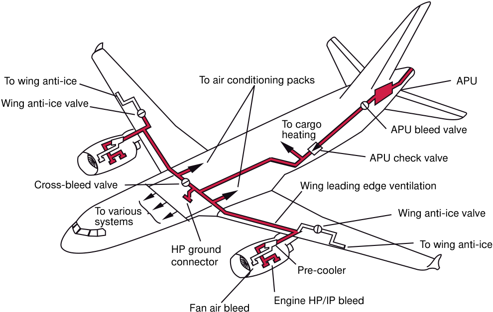
Section titled “2 Description of the pneumatic system”The main purpose of the dual bleed air system is to provide the air conditioning system with air regulated in both pressure and temperature. They also supply various air system consumers such as :
-
Wing anti-ice protection
-
Engine starter
-
Hydraulic reservoir and water tank pressurizatio n.
-
New maintenance and design improvements should reduce the number of such events in the future.
We are confident that the correct application of the above procedures and improvements should help airlines to limit occurrences of dual bleed loss incidents.
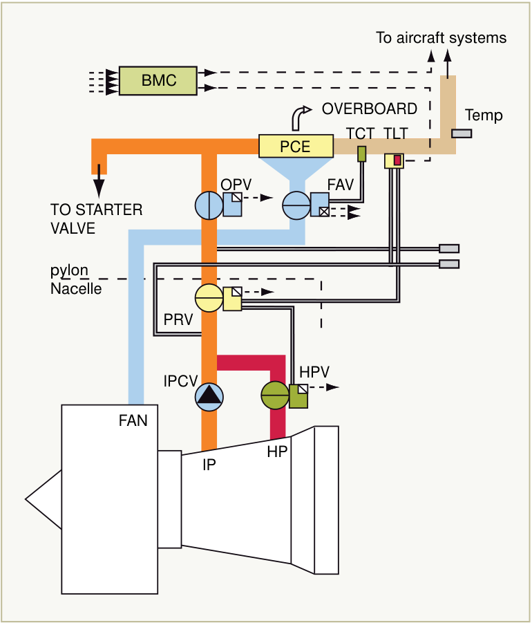
The bleed air system is installed in the nacelle and pylon of each engine and includes:
-
For the pressure regulation:
-
An Intermediate Pressure Bleed Check Valve (IPCV)
-
A High Pressure Bleed Valve (HPV)
-
An Over Pressure Valve (OPV)
-
A Pressure Regulator Bleed Valve (PRV), which is commanded by a Temperature Limitation Thermostat (TLT). The TLT will order the PRV to reduce the pressure in the system in case of overtemperature.
-
For the temperature regulation:
-
A precooler exchanger (PCE)
-
A Fan Air Valve (FAV), which is commanded by a Temperature Control Thermostat (TCT)
-
– The TCT will order the FAV to increase air flow from the fan in case of over-temperature.
-
For the system monitoring:
-
A Bleed Monitoring Computer (BMC).
3 Typical failure scenario
Section titled “3 Typical failure scenario”The dual bleed loss events usually happen when one bleed fails, resulting in the remaining bleed on the other engine to compensate for it.
The augmented flow of warm air from the engine core leads to a corresponding increase in the flow of cold air from the Fan to the Precooler.
In case of one engine bleed loss, the remaining bleed fails when the Fan Air Valve (FAV) does not let enough cold air reach the Precooler (PCE). This causes the temperature downstream of the PCE to reach the 260°C (500°F) over-temperature threshold, which induces the automatic closure of the bleed system.
This excessive rise in temperature is caused mainly by either:
-
Leakage of the TCT to FAV sense line
-
TCT drift / failure
-
Or FAV leakage / failure.
4 Operational procedure to be applied
Section titled “4 Operational procedure to be applied”NOTE: In-service experience has shown that the root cause of over-temperature is often linked to a combination of the above factors.
Other possible causes are:
-
Temperature sensor failure
-
Wiring failure.
In the above scenario, the failure of the first bleed system leaves the second engine bleed to supply all the aircraft consumers. This bleed, in turn, is lost due to excessive demand.
After the failure of both bleed systems, the AIR DUAL BLEED FAULT paper procedure (QRH page 2.02 and FCOM 3.02.36 page 3) therefore recommends to initiate a rapid descent to FL200 and to reduce air demand, before attempting the recovery of the second bleed system.
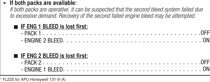
Assuming that both PACKS are operative, the air demand is reduced by shutting OFF the PACK on the side of the first affected bleed system. The flight crew should then press twice the ENG BLEED pushbutton on the overhead panel associated to the second engine bleed, in order to reset it.
- DESCENT … … … … … … … … … … … … … . INITIATE Descend rapidity to FL200* so that the bleed supply may be supplied by the APU, if the bleed system recovery is not successful.
The bleed should recover, and the flight should be able to resume to the destination airport with one engine bleed supplying one PACK (that automatically delivers high flow).
5 Maintenance and design improvements
Section titled “5 Maintenance and design improvements”Following laboratory and flight tests, enhancements have been introduced in the domains of maintenance and design.
-
Maintenance
-
Improved FAV leak check procedure in the Aircraft Maintenance Manual (AMM) (ref A)
-
– Test of the engine bleed system performance. The AMM includes a new test of the capacity of the bleed system to function properly in a one bleed/two packs configuration (ref B)
-
Design
-
The TCT has been modified to react faster to excessive temperatures, thereby ordering the FAV to increase the cold air supply earlier than before (ref D)
-
In order to address the leakage issue, the FAV has been modified to include a seal between the actuator and actuator cover (ref E)
-
The pressure limitation function has been shifted. Even though the TLT function is not a root cause of bleed failure, it is considered to be an aggravating factor for an already degraded system (ref F)
-
New tooling is being developed to allow bleed air system health checks and to improve trouble shooting efficiency. These tools are expected to be available by the end of 2009.
6 Conclusion
Section titled “6 Conclusion”-
Periodic cleaning of the TCT filter
-
As the clogging of the filter is considered to be a major contributor to the TCT temperature drift, a new mandatory MPD task has been introduced (ref C).
The root causes of the dual bleed loss scenario have been identified. Necessary prevention and design improvements have been put in place to address this issue.
- NOTE: The Aircraft Condition Monitoring System (ACMS) may be customized to monitor bleed temperature levels. This allows preventive troubleshooting to be performed before the bleed actually fails.
Incorporation of the below enhancements should address the large majority of dual bleed loss occurrences. This will have a positive impact on our customer airlines’ operations. We therefore highly recommend their timely application.
REFERENCES
Section titled “REFERENCES”A) AMM task 36-11-54-720-001-01 B) AMM task 36-11-00-710-003 C) MPD Task 361143-01-1
- D) AIRBUS SB A320-36-1061 and LIEBHERR VSB 342-36-08
E) LIEBHERR VSB 6730F-36-01 & 6730-36-03 F) LIEBHERR VSB 341-36-06
Please consult the Retrofit Information Letter (ref. SEOT2 916.0468/08) issued in July 2008 for logistical advice on the completion of the A320 family dual bleed loss improvement action plan.
作者:Patrick GRAVE 引气、防冰与防火系统客户服务中心经理
Christophe MATHE A320/A330/A340运营标准客户服务中心工程师
过去几年,A320系列机队发生了大量双发动机引气失效事件。这些失效的后果从起飞后不久的空中返航,到完全的客舱释压事件和航班备降不等。
本文旨在介绍双引气失效的典型原因,并解释:
- 机组如何通过应用相关程序来减轻此类事件的操作后果
2 引气系统描述
Section titled “2 引气系统描述”双引气系统的主要目的是为空调系统提供经过压力和温度调节的空气。它们还为各种引气用户提供气源,例如:
-
机翼防冰保护
-
发动机启动器
-
液压油箱与水箱增压
-
新的维护和设计改进将减少此类事件的发生。
我们相信,正确应用上述程序和改进措施将帮助航空公司减少双引气失效事件的发生。
引气系统安装在每台发动机的短舱和吊挂上,包括:
-
压力调节部分:
-
中压引气单向活门(IPCV)
-
高压引气活门(HPV)
-
超压活门(OPV)
-
压力调节引气活门(PRV),由温度限制恒温器(TLT)控制。当出现超温时,TLT将指令PRV降低系统中的压力。
-
温度调节部分:
-
预冷却器(PCE)
-
风扇空气活门(FAV),由温度控制恒温器(TCT)控制
-
当出现超温时,TCT将指令FAV增加来自风扇的冷空气流量。
-
系统监控部分:
-
引气监控计算机(BMC)
3 典型失效场景
Section titled “3 典型失效场景”双引气失效事件通常发生在一套引气失效后,另一台发动机的引气需要补偿该损失的情况下。
来自发动机核心的暖空气流量的增加会导致从风扇到预冷却器的冷空气流量相应增加。
在一台发动机引气失效的情况下,当风扇空气活门(FAV)没有让足够的冷空气到达预冷却器(PCE)时,剩余的引气将失效。这导致PCE下游温度达到260°C(500°F)超温阈值,从而导致引气系统自动关闭。
温度的过度升高主要由以下原因引起:
-
TCT到FAV感应管路泄漏
-
TCT漂移/失效
-
或FAV泄漏/失效
4 应执行的操作程序
Section titled “4 应执行的操作程序”注意:实际使用经验表明,超温的根本原因通常与上述因素的组合有关。
其他可能的原因包括:
-
温度传感器失效
-
线路失效
在上述场景中,第一套引气系统的失效使得第二台发动机的引气需要供应飞机的所有用户。随后,这套引气也因过度需求而失效。
在两套引气系统都失效后,AIR DUAL BLEED FAULT纸质程序(QRH第2.02页和FCOM 3.02.36第3页)因此建议:在尝试恢复第二套引气系统之前,执行快速下降至FL200并减少用气需求。
假设两部PACK正常工作,通过关闭第一套受影响引气侧的PACK来减少用气需求。随后,机组应按两次 overhead 面板上与第二台发动机引气相关的ENG BLEED按钮,以复位引气。
- DESCENT … … … … … … … … … … … … … . INITIATE 快速下降至FL200,以便如果引气系统恢复不成功,可由APU提供引气。
引气应恢复正常,航班可以继续飞往目的地机场,由一台发动机的引气供应一部PACK(自动提供高流量)。
5 维护与设计改进
Section titled “5 维护与设计改进”经过实验室和飞行测试后,在维护和设计领域引入了改进措施。
-
维护
-
优化了《飞机维护手册》(AMM) 中的 FAV 渗漏检查程序(参考文献 A)
-
– 发动机引气系统性能测试。AMM 包含了引气系统在单引气/双空调组件构型下正常工作的能力测试(参考文献 B)
-
设计
-
TCT 经过改进,对过高温度的响应更快,从而更早地指令 FAV 增加冷气供应(参考文献 D)
-
为解决渗漏问题,FAV 经过改进,在执行机构和执行机构盖之间增加了密封圈(参考文献 E)
-
压力限制功能已移位。尽管 TLT 功能不是引气失效的根本原因,但被认为是系统已退化情况下的一个加重因素(参考文献 F)
-
正在开发新工具以实现引气系统健康检查并提高排故效率。该工具预计于 2009 年底前可用。
-
定期清洁 TCT 滤芯
-
由于滤芯堵塞被认为是导致 TCT 温度漂移的主要原因,已引入一项新的强制性 MPD 任务(参考文献 C)。
双引气丢失场景的根本原因已被确认。必要的预防措施和设计改进已经到位,以解决此问题。
- 注意:飞机状态监控系统 (ACMS) 可以定制以监控引气温度水平。这使得可以在引气实际失效之前进行预防性排故。
纳入以下改进措施应能解决大多数双引气丢失事件。这将对客户航空公司的运营产生积极影响。因此,我们强烈建议及时实施。
A) AMM task 36-11-54-720-001-01 B) AMM task 36-11-00-710-003 C) MPD Task 361143-01-1
D) AIRBUS SB A320-36-1061 and LIEBHERR VSB 342-36-08
E) LIEBHERR VSB 6730F-36-01 & 6730-36-03 F) LIEBHERR VSB 341-36-06
请参阅 2008 年 7 月发布的改装信息函(编号 SEOT2 916.0468/08),以获取关于完成 A320 系列双引气丢失改进行动计划的后勤建议。