Let's Use xLS
Source: Airbus Safety First URL: https://safetyfirst.airbus.com/lets-use-xls/ Published: 2025-06-05 Category: Flight Ops, approach, FLS, GLS, guidance, ILS, landing, Non-precision approaches, NPA, SLS PDF: Original PDF

Letʼs Use xLS
Section titled “Letʼs Use xLS”xLS is a concept that has been developed by Airbus for A320 family, A330, A350, and A380 aircraft to ease the flight crew’s task of flying all straight approaches. It is now the standard for all the newly manufactured Airbus aircraft of these types.
This article describes the xLS concept, its various functions, their advantages, and why xLS has been chosen as the standard for flying straight approaches on Airbus aircraft. It addresses operational and training considerations and highlights the benefits of using xLS. It also explains how to retrofit the xLS functions to take advantage of this innovation on earlier produced aircraft.
Check the latest version of this article on safetyfirst.airbus.com and on the Safety first app for iOS and Android devices.
XLS CONCEPT
Section titled “XLS CONCEPT”Every day, around the world, many final approaches flown by commercial jet aircraft are Instrument Landing System (ILS) approaches. Flight crews are therefore very familiar with flying ILS approaches. In comparison, Non-Precision Approaches (NPA) represent a smaller proportion of the approaches performed daily. However, 50 % of recorded Controlled Flight Into Terrain (CFIT) during approach and Runway Undershoot accidents occurred while flying an NPA.
In most of these accidents, the identified contributing factors included:
-
Lack or loss of situational awareness (lateral or vertical)
-
Difficulties to efficiently control, monitor or adjust the vertical flight path
-
High crew workload
xLS: A Common Way to Fly all Straight Approaches
Section titled “xLS: A Common Way to Fly all Straight Approaches”To address these factors, Airbus developed the xLS concept for A320 family, A330, A350, and A380 aircraft to ease the flight crewʼs task of flying all straight approaches.
This is why xLS provides a common and consistent Human-Machine Interface (HMI) and 3D guidance based on the well-known ILS function for all straight approaches. Aircraft handling with the various xLS functions is identical, allowing operational procedures to be almost identical for all straight approaches.
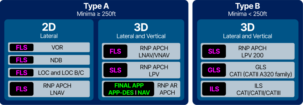
The xLS concept applies to both 2D and 3D approaches. xLS gathers 4 functions to fly all straight approaches (fig.1) :
-
Instrument Landing System (ILS) for ILS approaches,
-
GBAS Landing System (GLS) for GLS approaches ,
-
SBAS Landing System (SLS) for RNP approaches with LPV minima, and
-
● FMS Landing System (FLS) for 2D (VOR, NDB, LOC, LOC B/C, RNP with LNAV minima) and 3D (RNP with LNAV/VNAV minima) approaches.
FINAL APP (A320 Family, A330) and APP-DES I NAV (A350 and A380) guidance modes remain for flying curved approaches.
(fig.1) ICAO Approach types with their corresponding Airbus approach functions
XLS FUNCTIONS
Section titled “XLS FUNCTIONS”Use of a Virtual Beam for GLS, SLS and FLS
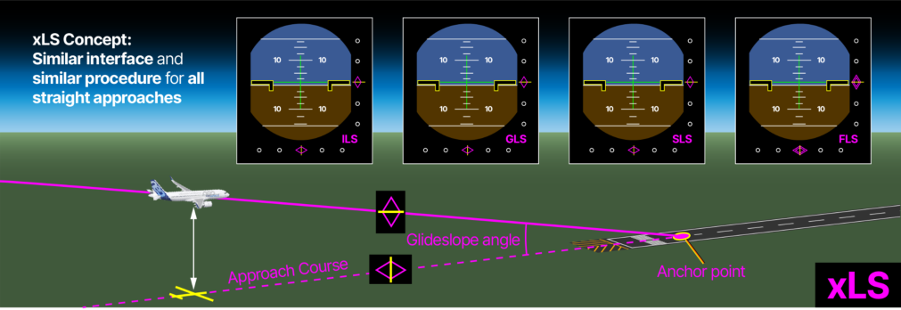
Section titled “Use of a Virtual Beam for GLS, SLS and FLS”GLS, SLS and FLS have a common principle: the use of a virtual beam, similar to an ILS beam (localiser + glideslope), computed by the Multi Mode Receiver (MMR) (fig.2). The MMR uses an anchor point , generally the runway threshold, an approach course , and a glideslope angle. It then uses the aircraftʼs position and altitude to compute deviations with regards to the virtual beam.
The computed deviations are then displayed on the PFD in a way similar to the ILS deviations. They are also sent to the autoflight system to compute guidance commands for the Flight Director (FD) and AutoPilot (AP).
(fig.2) xLS concept
Different data sources for virtual beam and deviations computation
Section titled “Different data sources for virtual beam and deviations computation”The main difference among GLS, SLS, and FLS is the source of the data (aircraft position, aircraft altitude, and virtual beam characteristics) used to compute deviations of the aircraft’s position with regard to the virtual beam.
For more information on the xLS functions, refer to the “Flying xLS on all Airbus Fleet” video available on the Airbus Worldwide Instructor News (WIN) portal.
FLS function
Section titled “FLS function”The FLS function does not depend on any ground navaid to compute deviations.
FLS uses FMS position and barometric altitude for deviations computation
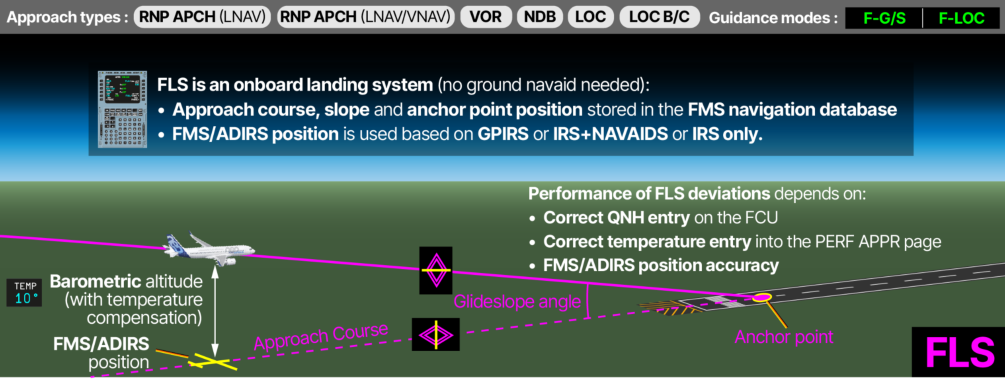
Section titled “FLS uses FMS position and barometric altitude for deviations computation”FLS utilizes the aircraft’s position, computed by the FMS (A320, A330, A380) or ADIRS (A350) through mixed GPS/IRS (GPIRS), mixed IRS/radio NAVAIDs, or pure IRS, for lateral deviation computation (fig.3). Additionally, FLS uses the aircraftʼs barometric altitude to compute the vertical deviation.
FLS virtual beam characteristics are stored in the FMS navigation database
Section titled “FLS virtual beam characteristics are stored in the FMS navigation database”FLS uses the virtual beam characteristics that are stored in the FMS navigation database.
FLS glideslope low temperature compensation An interesting feature is that FLS uses the temperature entered into the FMS APPROACH page to compensate the glideslope for low temperatures when the OAT is below ISA temperature. Specific F-G/S and F-LOC guidance modes for FLS FLS uses specific F-G/S and F-LOC guidance modes that have similar behavior (engagement and disengagement) to the G/S and LOC modes. FLS performance Correct FLS deviations rely on: ● A correct QNH or QFE selection on the FCU ● A correct temperature entry in the PERF APPR page of the FMS for cold temperature compensation ● A good aircraft position performance The interface is adapted to highlight that FLS does not provide the same performance as for a precision approach. For example, “Double diamonds” are (fig.3) FMS Landing used instead of single diamonds to indicate the FLS deviations. System (FLS)
For more information on the use of FLS, refer to:
-
FCOM “Procedures - Normal Procedures - Standard Operating Procedures - Approach - Approach Guidance Management - Approach using F-LOC F-G/S Guidance”,
-
● FCTM “Procedure - Normal Procedure - Standard Operating Procedure - Approach - Guidance Management - Approach using FLS function”, and
-
● The “Operational Use of FLS” video available on the Airbus WIN website.
FLS advantages compared to** FINAL APP **for straight approaches
Section titled “FLS advantages compared to** FINAL APP **for straight approaches”Using the FLS function offers several advantages compared to the FINAL APP mode: ILS look-alike
FLS, being part of the xLS concept, offers a similar interface, a similar aircraft guidance, and a similar operational procedure as ILS whereas FINAL APP has a specific interface and a specific behavior that requires a different procedure.
Flexibility of FLS beam capture
Section titled “Flexibility of FLS beam capture”FLS beam capture, like ILS beam capture, is independent of flight plan sequencing. It is therefore flexible and can easily cope with ATC constraints (vectoring) or approaches optimization strategies. In comparison, FINAL APP engagement can only be performed within a restricted window and requires proper flight plan sequencing.
FLS can be used when the temperature is below the published minimum OAT
With the FLSʼs temperature compensation, the managed F-G/S I F-LOC FLS modes can be used when the destination temperature is below the published minimum temperature for an RNP approach with LNAV/VNAV minima, or below the minimum temperature defined by airline policy for temperature correction. FINAL APP mode is not compensated for low temperatures therefore it cannot be used below the published minimum temperature or below the minimum temperature defined by airline policy for temperature correction. Additionally, a manual temperature correction of the intermediate segment’s altitude (deceleration platform) could prevent FINAL APP engagement if the aircraft altitude is outside the vertical engagement conditions.
Vertical managed guidance for LOC-only, LOC B/C and ILS with G/S out approaches
The F-G/S vertical guidance mode of FLS can be used in combination with the LOC or LOC B/C mode to provide managed vertical guidance during LOC-only, LOC B/C, and ILS with G/S out approaches. This represents a significant safety improvement compared to the use of selected vertical FPA I LOC or FPA I LOC B/C modes, which require a higher crew workload.
SLS function
Section titled “SLS function”SLS function uses geometric position and altitude to compute deviations
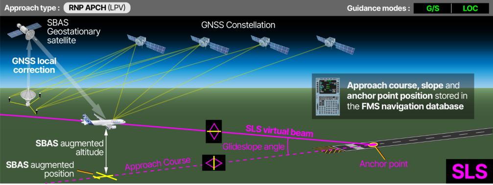
Section titled “SLS function uses geometric position and altitude to compute deviations”SLS uses an augmented GNSS signal provided by both the Global Positioning System (GPS) constellation and a Satellite-Based Augmentation System (SBAS) service to compute the aircraftʼs position and altitude (fig.4). This increased performance enables the aircraft to fly RNP APCH with LPV minima down to 200ft (equivalent to CAT I).
SLS virtual beam characteristics are stored in the FMS navigation database
Section titled “SLS virtual beam characteristics are stored in the FMS navigation database”The characteristics of the SLS virtual beam are stored in the FMS navigation database.
G/S and LOC guidance modes
Section titled “G/S and LOC guidance modes”SLS uses the same G/S and LOC guidance modes as ILS.
FLS as a backup
Section titled “FLS as a backup”In the event of a loss of the SLS function, the FLS function can be used as a backup to fly the same RNP approach, but down to LNAV/VNAV minima. FLS installation is therefore a prerequisite for SLS.
GLS function
Section titled “GLS function”GLS function uses geometric position and altitude to compute deviations
Section titled “GLS function uses geometric position and altitude to compute deviations”(fig.4) SBAS Landing System (SLS)
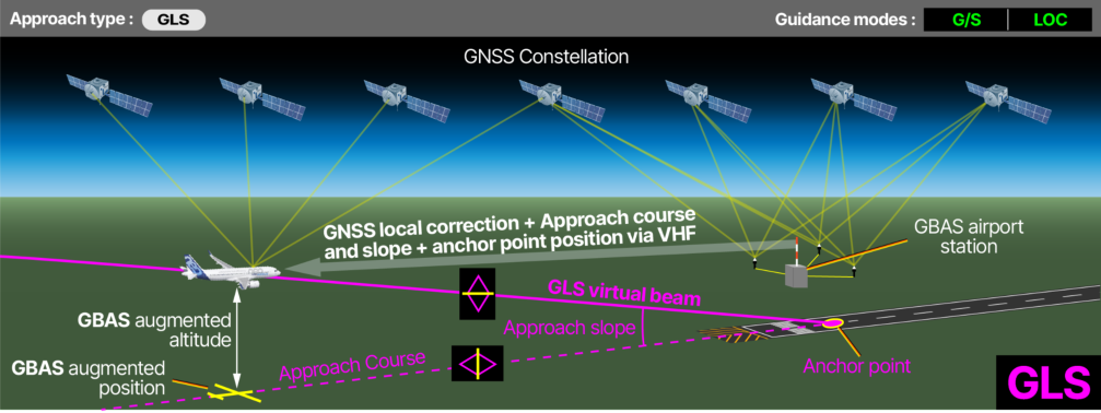
GLS uses an augmented GNSS signal provided by both the Global Positioning System (GPS) constellation and a Ground-Based Augmentation System (GBAS) station to compute the aircraft’s position and altitude (fig.5). This increased performance enables the aircraft to fly GLS CAT I (CAT II on A320 family) approaches with autoland.
Like ILS, GLS can be used for takeoff to provide the flight crew with assistance in maintaining the runway axis.
GLS virtual beam characteristics are sent by the GBAS ground station
Section titled “GLS virtual beam characteristics are sent by the GBAS ground station”GLS receives the virtual beam characteristics from the GBAS airport station via VHF. Consequently, if the FMS is not available, the flight crew can manually tune the GLS channel on the Radio Management Panel (RMP) to fly a GLS approach, similar to how they can manually tune the ILS frequency for an ILS approach.
G/S and LOC guidance modes
Section titled “G/S and LOC guidance modes”GLS uses the same G/S and LOC guidance modes as ILS.
(fig.5) GBAS Landing System (GLS)
OPERATIONAL CONSIDERATIONS
Section titled “OPERATIONAL CONSIDERATIONS”The introduction of the xLS concept is a significant improvement with minor changes in the flight crewʼs routine. They need to know which xLS functions are available on the aircraft they are flying, and fly their straight approach like an ILS when the associated xLS function is available.
Which xLS Functions are Installed on my Aircraft
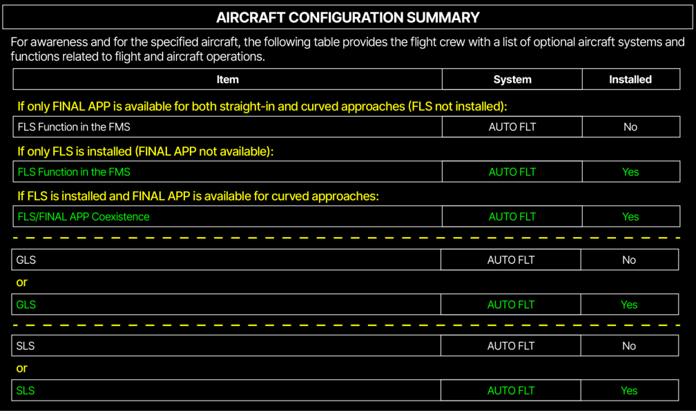
Section titled “Which xLS Functions are Installed on my Aircraft”During Preliminary Cockpit Preparation, the flight crew can quickly identify which xLS functions are available on the aircraft by referring to the Aircraft Configuration Summary table in the FCOM/QRH (fig.6).
FLS is not mentioned in the table for A350 and A380 aircraft, as it is installed on all aircraft.
(fig.6) The Aircraft Configuration Summary provides the list of available xLS functions
FLS only** vs **FLS/FINAL APP Coexistence
Section titled “FLS only** vs **FLS/FINAL APP Coexistence”In the early stage of FLS introduction on A320 family and A330 aircraft, it was only possible to have either FLS or FINAL APP available due to some computer standard restrictions. The coexistence between FLS and FINAL APP was quickly introduced to enable operators that fly curved approaches to also take advantage of FLS for their straight approaches.
Only 84 A320 family aircraft and 41 A330 aircraft were initially fitted with FLS only. All other aircraft with FLS have the FLS/FINAL APP coexistence.
The cross-reference table in the FCOM’s “Procedure - Normal Procedures SOP Approach General” chapter provides the recommended guidance mode for each type of approach and a link to the relevant procedure.
Fly your Straight Approaches Like an ILS
Section titled “Fly your Straight Approaches Like an ILS”If the corresponding xLS functions are available on the aircraft, the methods to fly straight approaches and ILS are similar:
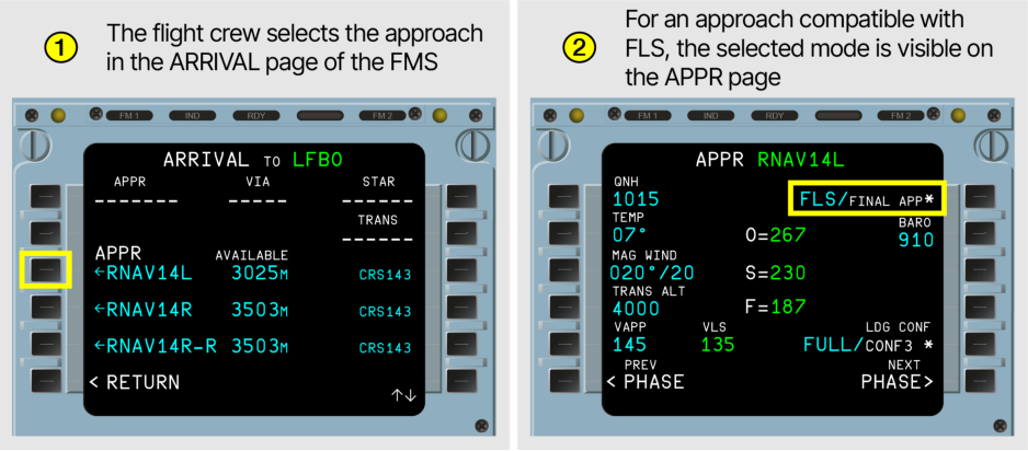
① The flight crew selects the approach in the ARRIVAL page of the FMS. The associated xLS function is automatically selected, if available. ② For an approach compatible with FLS, the selected function is displayed on the APPR page of the FMS.
(fig.7) How to fly an approach using xLS - part 1
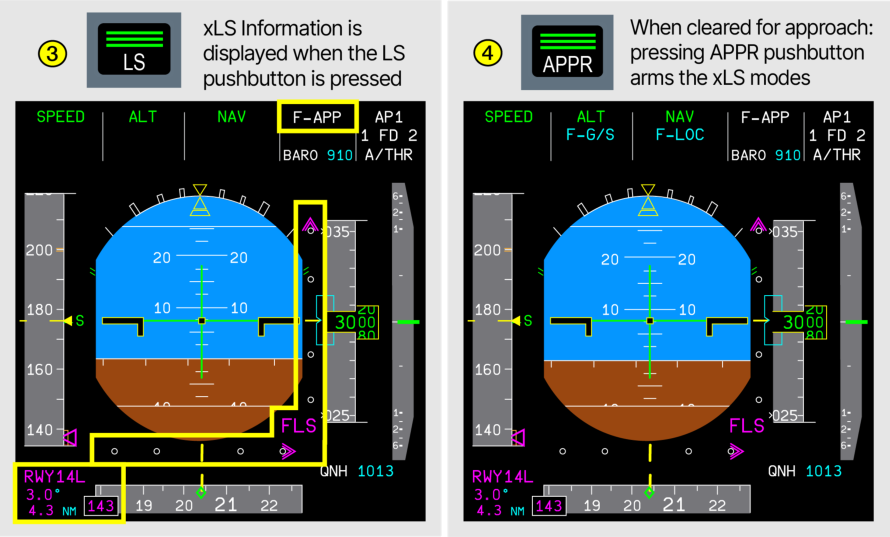
③ The xLS information appears on the PFD and ND when the flight crew presses the LS pushbutton. ④ When cleared for the approach and on the intercept trajectory to the final approach course, with LOC deviation available, the PF presses the APPR pushbutton to arm the xLS guidance modes: ● F-G/S I F-LOC modes for VOR, NDB, and RNP approach with LNAV or LNAV/VNAV minima
-
F-G/S I LOC modes for LOC-only or ILS with G/S out approaches
-
● F-G/S I LOC B/C modes for LOC B/C approaches ● G/S I LOC modes for GLS approaches, and RNP approaches with LPV minima flown with SLS.
(fig.8) How to fly an approach using xLS - part 2
⑤ Then, depending on the approach type, the F-LOC, LOC, or LOC B/C lateral (fig.9) How to fly an mode engages, ⑥ followed by the F-G/S or G/S vertical mode to start the final approach using xLS - descent. part 3
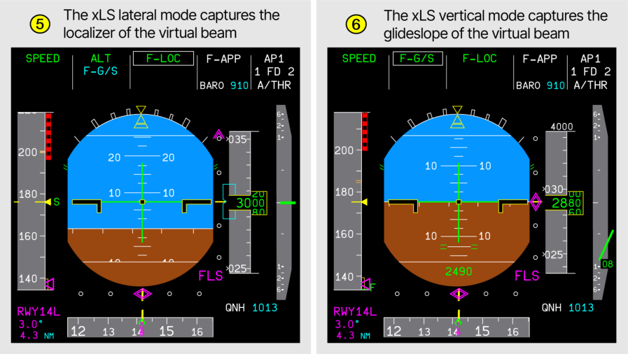
The FCOM and FCTM provides all the necessary information on the use of the xLS functions. The cross-reference table in FCOM SOP “Approach” provides the preferred guidance modes for each type of approach.
TRAINING CONSIDERATIONS
Section titled “TRAINING CONSIDERATIONS”Limited training needs
Section titled “Limited training needs”As explained earlier in this article, the only difference between the xLS functions is the source of the data used for the deviations computation. The way to fly all xLS functions is identical, and the guidance is identical. The SOP for all xLS functions are therefore almost identical with a slight difference for FLS in the case of a degradation of the aircraft position performance.
This is why only Level A (self-instruction) training is needed for SLS and GLS, and Level B (aided instruction) training is needed for FLS.
Simulator data packages are available
Section titled “Simulator data packages are available”For operators wishing to add the xLS to their simulators, xLS functions are available in the following simulator data package:
Table 1: Simulator data packages for xLS
| Aircraft type | FLS | SLS | GLS | |
|---|---|---|---|---|
| A320 family | Std 2.1 | Std 2.2 | Std 2.0 | |
| A330 | Std | 3.0 (updated in 3.1) | Std 3.1 | Std 2.6 |
| A350 | Std 1.0 | Std 1.0 | Std 1.0 | |
| A380 | Std 1.4 | Std 1.5 | Std 1.4 |
XLS FUNCTIONS AVAILABILITY
Section titled “XLS FUNCTIONS AVAILABILITY”The sections below indicate for each aircraft type whether the various xLS functions are installed as a standard from aircraft delivery or if they are optional. They also list the minimum computer standards required to retrofit the functions on in-service aircraft.
A320 Family Aircraft
Section titled “A320 Family Aircraft”FLS is installed by default on A320 family aircraft manufactured from 2022. It can be retrofitted on previously built aircraft, provided they are equipped with the minimum computer standards.
GLS and SLS are optional. They are available in line-fit (i.e., from the production line) or as a retrofit on in-service aircraft via Service Bulletin.
| Aircraft | FLS | GLS | SLS |
|---|
Table 2: xLS functions availability on A320 family aircraft
|---|---|---|---|---|---|---|---|---|---|---| |||HWL|Thales|HWL|Collins|||HWL|ACSS||
Table 3: Minimum computer standards required for xLS activation on A320 family aircraft
A330 Aircraft
Section titled “A330 Aircraft”FLS is installed by default on A330 aircraft manufactured from 2020. It can be retrofitted on previously built aircraft, provided they are equipped with the minimum computer standards.
GLS and SLS are optional. They are available in line-fit (i.e., from the production line) or as a retrofit on in-service aircraft via Service Bulletin.
| Aircraft | FLS | GLS | SLS |
|---|
Table 4: xLS functions availability on A330 aircraft
|---|---|---|---|---|---|---|---|---|---|---| |||HWL|Thales|Honeywell|Collins|||Honeywell|ACSS||
Table 5: Minimum computer standards required for xLS activation on A330 aircraft
A350 Aircraft
Section titled “A350 Aircraft”FLS is installed by default on every A350 aircraft. Coexistence with APP-DES mode is also available to fly curved approaches. GLS and SLS are optional and are available as a single package.
| Aircraft | FLS | GLS | SLS |
|---|---|---|---|
| A350 aircraft | Basic | Optional | Optional |
Table 6: xLS functions availability on A350 aircraft
A380 Aircraft
Section titled “A380 Aircraft”FLS was installed by default on every A380 aircraft. Coexistence with APP-DES mode is also available to fly curved approaches on aircraft equipped with Avionic Batch 7 and the RNP AR modification. GLS and SLS are optional.
| Aircraft | FLS | GLS | SLS |
|---|---|---|---|
| A380 aircraft | Basic | Optional | Optional |
Table 7: xLS functions availability on A380 aircraft
LET’S USE XLS
Section titled “LET’S USE XLS”We have described the numerous operational and safety benefits of xLS to fly all straight approaches, so let’s use xLS!
Letʼs Use FLS
Section titled “Letʼs Use FLS”Now that FLS is standard on every newly produced aircraft, letʼs also benefit from FLS on the previously built A320 family and A330 aircraft.
Many A320 family and A330 aircraft can be retrofitted with FLS
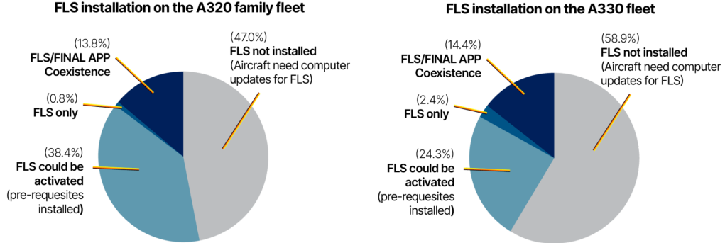
Section titled “Many A320 family and A330 aircraft can be retrofitted with FLS”38.4% of the current A320 Family aircraft fleet have all the prerequisites to activate FLS. This represents more than 4,000 aircraft that could easily activate the FLS function.
Similarly, 24.3% of the A330 aircraft fleet, which represents more than 350 aircraft, could activate the FLS function without any additional computer update.
(fig.10) FLS installation status for A320 family and A330 fleet in April 2025
A short grounding time to activate FLS
Section titled “A short grounding time to activate FLS”The maintenance task to activate the FSL function takes 2.5 hours for an aircraft with all the minimum prerequisites.
Attractive commercial conditions for the retrofit of FLS
Section titled “Attractive commercial conditions for the retrofit of FLS”To encourage operators to retrofit the FLS function on their in-service aircraft, Airbus proposes very attractive commercial conditions for the FLS activation Service Bulletin. Operators can contact their Customer Support Directors for more information and to perform an analysis of their fleet’s retrofit possibilities.
Letʼs Use SLS
Section titled “Letʼs Use SLS”An increasing number of published RNP approach with LPV minima
Section titled “An increasing number of published RNP approach with LPV minima”As of early 2025, more than 7 000 RNP approaches with LPV minima are operational in SBAS-covered areas, including Europe, the U.S., South Korea, Japan, and India. The number of RNP approaches with LPV minima is now greater than the number of ILS approaches in the U.S.A. SBAS coverage for Africa, Australia, and China is also planned in the near future.
EASA Regulation for CAT I operation post 2030 in Europe
Section titled “EASA Regulation for CAT I operation post 2030 in Europe”The European (EU) IR 2018/1048 regulation published by EASA requests exclusive use of Performance Based Navigation (PBN) for non-CAT II/CAT IIIA/CAT IIIB operations. This means that SLS should be selected by airlines to maintain CAT I equivalent operations in Europe after June 6, 2030.
Potential for an SLS CAT I autoland
Section titled “Potential for an SLS CAT I autoland”To increase the availability of automatic landings, Airbus is currently assessing the possibility of certifying an SLS CAT I autoland.
Contributors:
Section titled “Contributors:”Julien BERNAGE
Section titled “Julien BERNAGE”Senior Flight Operations Engineer Approach and Landing specialist Customer Support
Dirk DE-WINTER Flight Ops & Training Expert Pilot Customer Support
Maxime LANSONNEUR Director Safety - Training and Flight Operations Customer Support
Caroline PORTALES Navigation Systems Manager Design Office
The introduction of the xLS concept on A380 and A350 aircraft brought a significant operational and safety improvement by enabling all straight approaches to be flown like an ILS.
In the spirit of continuous enhancement, Airbus decided to also bring xLS to A320 family and A330 aircraft. While SLS and GLS remain optional, FLS is now standard for all newly built A320 family and A330 aircraft, as it is for A350 aircraft.
Many in-service A320 family and A330 aircraft can also benefit from xLS, as more than 4 000 of them have all the prerequisites to activate the FLS function. A significant part of the remaining aircraft could also benefit from FLS but with some additional system updates.
The increasing number of RNP approaches with LPV minima and the EASA regulation requesting the exclusive use of PBN for CAT I operations also highlight the operational benefits of using SLS.
Airbus encourages operators to contact their Customer Support Directors to analyze their fleet and organize the retrofit of their aircraft with xLS.
Ricardo RAMIREZ HERNANDEZ Upgrade Services Marketing
Patrice ROUQUETTE Mission and Flight Operations Expert Design Office
With thanks to Cedric DESCHEEMAEKER from the Aviation Safety team
Safety first, 2025. Safety first is published by Airbus S.A.S. 1, rond point Maurice Bellonte - 31707 Blagnac Cedex/France.
Editor: Yannick Malinge, SVP Aviation Safety.
Editorial team: Guillaume Estragnat, Vanessa Sadi, Gwyneth Duggan, Javier Martinez Marina, Bruno Fargeon.
Photos by Airbus.
让我们使用 xLS
Section titled “让我们使用 xLS”xLS 是空客为 A320 系列、A330、A350 和 A380 飞机开发的一个概念,旨在减轻飞行机组执行所有直线进近的负担。如今,这已成为这些型号所有新生产空客飞机的标准配置。
本文描述了 xLS 概念及其各项功能、优势,以及为什么 xLS 被选为空客飞机执行直线进近的标准方法。本文涉及运营和培训方面的考虑,并强调了使用 xLS 的好处。同时还解释了如何在早期生产的飞机上加装 xLS 功能以利用这一创新技术。
请在 safetyfirst.airbus.com 以及 iOS 和 Android 设备上的 Safety First 应用上查看本文的最新版本。
XLS 概念
Section titled “XLS 概念”每天,全球各地商业喷气飞机的许多最后进近都是仪表着陆系统 (ILS) 进近。因此,飞行机组对执行 ILS 进近非常熟悉。相比之下,非精密进近 (NPA) 在每日执行的进近中占比较小。然而,在进近和跑道未达事故中,50% 的记录在案的撞地可控飞行 (CFIT) 事故发生在执行 NPA 期间。
在这些事故中,已识别的促成因素包括:
- 态势感知缺失或丧失(侧向或垂直)
- 难以有效控制、监控或调整垂直飞行轨迹
- 机组工作负荷高
xLS:一种统一执行所有直线进近的方式
Section titled “xLS:一种统一执行所有直线进近的方式”为了解决这些因素,空客为 A320 系列、A330、A350 和 A380 飞机开发了 xLS 概念,以减轻飞行机组执行所有直线进近的负担。
这就是为什么 xLS 为所有直线进近提供了统一且一致的人机界面 (HMI) 和三维引导,基于众所周知的 ILS 功能。各种 xLS 功能的飞机操作方式相同,使得所有直线进近的运行程序几乎一致。
xLS 概念适用于二维和三维进近。xLS 汇总了 4 种功能以执行所有直线进近 (图 1):
- 仪表着陆系统 (ILS) 用于 ILS 进近,
- GBAS 着陆系统 (GLS) 用于 GLS 进近,
- SBAS 着陆系统 (SLS) 用于具有 LPV 最低标准的 RNP 进近,以及
- FMS 着陆系统 (FLS) 用于二维(VOR、NDB、LOC、LOC B/C、具有 LNAV 最低标准的 RNP)和三维(具有 LNAV/VNAV 最低标准的 RNP)进近。
FINAL APP(A320 系列、A330)和 APP-DES I NAV(A350 和 A380) 引导方式继续用于执行曲线进近。
(图 1) ICAO 进近类型及其对应的空客进近功能
XLS 功能
Section titled “XLS 功能”GLS、SLS 和 FLS 使用虚拟波束
Section titled “GLS、SLS 和 FLS 使用虚拟波束”GLS、SLS 和 FLS 有一个共同原理:使用由多模式接收机 (MMR) 计算的虚拟波束,类似于 ILS 波束(航向信标 + 下滑道)(图 2)。MMR 使用一个基准点(通常为跑道入口)、进近航道和下滑角。然后使用飞机位置和高度来计算相对于虚拟波束的偏差。
计算出的偏差随后以与 ILS 偏差类似的方式显示在 PFD 上。同时,这些偏差也被发送到自动飞行系统,以计算飞行指引仪 (FD) 和自动驾驶仪 (AP) 的引导指令。
(图 2) xLS 概念
虚拟波束和偏差计算的不同数据源
Section titled “虚拟波束和偏差计算的不同数据源”GLS、SLS 和 FLS 之间的主要区别在于用于计算飞机位置相对于虚拟波束偏差的数据源(飞机位置、飞机高度和虚拟波束特性)。
有关 xLS 功能的更多信息,请参阅空客全球教官新闻 (WIN) 门户上提供的“在所有空客机队上飞行 xLS”视频。
FLS 功能
Section titled “FLS 功能”FLS 功能不依赖任何地面导航设施来计算偏差。
FLS 利用 FMS 位置和气压高度计算偏差
Section titled “FLS 利用 FMS 位置和气压高度计算偏差”FLS 利用飞机位置(A320、A330、A380 由 FMS 计算,A350 由 ADIRS 计算),该位置通过 GPS/IRS 混合定位(GPIRS)、IRS/无线电导航台混合定位或纯 IRS 定位获得,用于计算水平偏差 (图 3)。此外,FLS 还利用飞机的气压高度来计算垂直偏差。
FLS 虚拟波束特性存储于 FMS 导航数据库中
Section titled “FLS 虚拟波束特性存储于 FMS 导航数据库中”FLS 使用存储在 FMS 导航数据库中的虚拟波束特性。
FLS 下滑道低温补偿 一个值得注意的功能是,FLS 使用输入到 FMS APPROACH 页面的温度值,当外界温度低于 ISA 温度时,对下滑道进行低温补偿。
F-G/S 和 F-LOC FLS 专用引导模式 FLS 使用专用的 F-G/S 和 F-LOC 引导模式,其行为(接通与断开)与 G/S 和 LOC 模式相似。
FLS 性能 正确的 FLS 偏差取决于:
- FCU 上正确选择 QNH 或 QFE
- FMS PERF APPR 页面中正确输入温度以进行低温补偿
- 飞机位置性能良好
界面经过适配以突出显示 FLS 无法提供与精密进近相同的性能。例如,使用 “双菱形” 标记代替单菱形来表示 FLS 偏差 (图 3)。
FMS 着陆系统 (FLS)
更多关于 FLS 使用的信息,请参阅:
- FCOM “程序 - 正常程序 - 标准操作程序 - 进近 - 进近引导管理 - 使用 F-LOC F-G/S 引导的进近”
- FCTM “程序 - 正常程序 - 标准操作程序 - 进近 - 引导管理 - 使用 FLS 功能的进近”
- Airbus WIN 网站上的 “FLS 运营使用” 视频
与 FINAL APP 相比,FLS 用于直线进近的优势
Section titled “与 FINAL APP 相比,FLS 用于直线进近的优势”使用 FLS 功能相比 FINAL APP 模式具有多项优势:
类 ILS 特性
FLS 作为 xLS 概念的一部分,提供与 ILS 相似的界面、飞机引导和操作程序,而 FINAL APP 具有独特的界面和特性,需要不同的程序。
FLS 波束截获的灵活性
Section titled “FLS 波束截获的灵活性”FLS 波束截获与 ILS 波束截获一样,不依赖于飞行计划排序。因此它更加灵活,能够轻松应对空中交通管制限制(雷达引导)或进近优化策略。相比之下,FINAL APP 只能在受限窗口内接通,且需要正确的飞行计划排序。
FLS 可在外界温度低于公布最低 OAT 时使用
借助 FLS 的温度补偿功能,管理模式的 F-G/S 和 F-LOC FLS 模式可在目的地温度低于 RNP 进近 LNAV/VNAV 最低标准公布的最低温度,或低于航空公司政策规定的温度修正最低温度时使用。FINAL APP 模式未进行低温补偿,因此不能用于低于公布最低温度或低于航空公司政策规定的温度修正最低温度的情况。此外,如果中间航段高度(减速平台)进行了人工温度修正,当飞机高度超出垂直接通条件时,可能导致 FINAL APP 无法接通。
用于仅 LOC、LOC B/C 和 G/S 失效 ILS 进近的垂直管理引导
FLS 的 F-G/S 垂直引导模式可与 LOC 或 LOC B/C 模式结合使用,在仅 LOC、LOC B/C 和 G/S 失效 ILS 进近中提供管理的垂直引导。与使用选择的垂直 FPA/LOC 或 FPA/LOC B/C 模式相比,这代表了显著的安全改进,后者需要更高的机组工作负荷。
SLS 功能
Section titled “SLS 功能”SLS 功能利用几何位置和高度计算偏差
Section titled “SLS 功能利用几何位置和高度计算偏差”SLS 利用由全球定位系统(GPS)卫星星座和星基增强系统(SBAS)服务提供的增强 GNSS 信号来计算飞机的位置和高度 (图 4)。这一增强性能使飞机能够执行 LPV 最低标准低至 200ft 的 RNP APCH(相当于 CAT I)。
SLS 虚拟波束特性存储于 FMS 导航数据库中
Section titled “SLS 虚拟波束特性存储于 FMS 导航数据库中”SLS 虚拟波束的特性存储在 FMS 导航数据库中。
G/S 和 LOC 引导模式
Section titled “G/S 和 LOC 引导模式”SLS 使用与 ILS 相同的 G/S 和 LOC 引导模式。
FLS 作为备份
Section titled “FLS 作为备份”如果 SLS 功能失效,FLS 功能可用作备份来执行相同的 RNP 进近,但最低标准为 LNAV/VNAV。因此,安装 FLS 是使用 SLS 的前提条件。
GLS 功能
Section titled “GLS 功能”GLS 功能利用几何位置和高度计算偏差
Section titled “GLS 功能利用几何位置和高度计算偏差”(图 4) SBAS 着陆系统 (SLS)
GLS 利用由全球定位系统(GPS)卫星星座和地基增强系统(GBAS)地面站提供的增强 GNSS 信号来计算飞机的位置和高度 (图 5)。这一增强性能使飞机能够执行 GLS CAT I(A320 系列为 CAT II)自动着陆进近。
与 ILS 一样,GLS 可用于起飞,为机组提供保持跑道轴线方面的辅助。
GLS 虚拟波束特性由 GBAS 地面站发送
Section titled “GLS 虚拟波束特性由 GBAS 地面站发送”GLS 通过 VHF 从 GBAS 机场站接收虚拟波束特性。因此,如果 FMS 不可用,飞行机组可以在无线电管理面板(RMP)上人工调谐 GLS 频道以执行 GLS 进近,类似于人工调谐 ILS 频率执行 ILS 进近的方式。
G/S 和 LOC 引导模式
Section titled “G/S 和 LOC 引导模式”GLS 使用与 ILS 相同的 G/S 和 LOC 引导模式。
(图 5) GBAS 着陆系统(GLS)
运行注意事项
Section titled “运行注意事项”xLS 概念的引入是一项重大改进,对飞行机组日常操作仅有微小变化。他们需要了解所飞机型上安装了哪些 xLS 功能,并在相应的 xLS 功能可用时,将直线进近当作 ILS 来飞。
我的飞机安装了哪些 xLS 功能
Section titled “我的飞机安装了哪些 xLS 功能”在驾驶舱准备阶段,飞行机组可通过查阅 FCOM/QRH 中的 飞机配置概要 表格快速确认飞机上可用的 xLS 功能**(图 6)**。
A350 和 A380 飞机的表格中未提及 FLS,因为该功能已安装在所有此类飞机上。
(图 6) 飞机配置概要提供可用 xLS 功能列表
仅 FLS** 与 **FLS/FINAL APP 共存
Section titled “仅 FLS** 与 **FLS/FINAL APP 共存”在 A320 系列和 A330 飞机引入 FLS 的早期阶段,由于计算机标准限制,只能选择 FLS 或 FINAL APP 之一。FLS 与 FINAL APP 共存功能很快被引入,使执行曲线进近的运营商也能利用 FLS 执行直线进近。
最初仅有 84 架 A320 系列飞机和 41 架 A330 飞机安装了仅 FLS 配置。所有其他安装 FLS 的飞机均具备 FLS/FINAL APP 共存功能。
FCOM”程序 - 正常程序 SOP 进近概述”章节中的交叉参考表格为每种进近类型提供推荐的引导模式,并链接至相关程序。
将直线进近当作 ILS 来飞
Section titled “将直线进近当作 ILS 来飞”如果飞机上安装了相应的 xLS 功能,执行直线进近的方法与 ILS 相似:
① 飞行机组在 FMS 的 ARRIVAL(进场)页面选择进近。相关的 xLS 功能将自动被选中(如可用)。② 对于与 FLS 兼容的进近,所选功能会显示在 FMS 的 APPR(进近)页面上。
(图 7) 如何使用 xLS 执行进近 - 第 1 部分
③ 按下 LS 按钮时,xLS 信息显示在 PFD 和 ND 上。④ 获得进近许可且处于最终进近航道的截获航迹上、LOC 偏差可用时,PF 按下 APPR 按钮以预位 xLS 引导模式:● 对于 VOR、NDB 以及带 LNAV 或 LNAV/VNV 最低标准的 RNP 进近:F-G/S I F-LOC 模式
● 对于仅 LOC 或无 G/S 的 ILS 进近:F-G/S I LOC 模式
● 对于 LOC B/C 进近:F-G/S I LOC B/C 模式● 对于 GLS 进近,以及使用 SLS 飞行的 LPV 最低标准的 RNP 进近:G/S I LOC 模式
(图 8) 如何使用 xLS 执行进近 - 第 2 部分
⑤ 然后,根据进近类型,F-LOC、LOC 或 LOC B/C 横向模式**(图 9)** 如何使用 xLS 执行进近 - 第 3 接通,⑥ 接着 F-G/S 或 G/S 垂直模式接通,开始最终部分进近下降。
FCOM 和 FCTM 提供使用 xLS 功能的所有必要信息。FCOM SOP”进近”中的交叉参考表格提供每种进近类型的首选引导模式。
培训注意事项
Section titled “培训注意事项”有限的培训需求
Section titled “有限的培训需求”如本文前文所述,xLS 各功能之间唯一的区别在于用于偏差计算的数据源。**所有 xLS 功能的飞行方法相同,引导方式相同。**因此,所有 xLS 功能的标准操作程序几乎相同,仅在飞机位置性能降级情况下 FLS 有细微差异。
这就是为什么 SLS 和 GLS 只需 A 级(自学)培训,而 FLS 需要 B 级(辅助教学)培训的原因。
模拟机数据包可用
Section titled “模拟机数据包可用”对于希望在其模拟机上增加 xLS 的运营商,xLS 功能可在以下模拟机数据包中获得:
表 1: xLS 模拟机数据包
| 机型 | FLS | SLS | GLS | |
|---|---|---|---|---|
| A320 系列 | Std 2.1 | Std 2.2 | Std 2.0 | |
| A330 | Std | 3.0(3.1 中更新) | Std 3.1 | Std 2.6 |
| A350 | Std 1.0 | Std 1.0 | Std 1.0 | |
| A380 | Std 1.4 | Std 1.5 | Std 1.4 |
xLS 功能可用性
Section titled “xLS 功能可用性”以下各节说明每种机型各种 xLS 功能是作为标准配置从飞机交付时即安装,还是作为选装配置。它们还列出对在役飞机进行改装的最低计算机标准要求。
A320 系列飞机
Section titled “A320 系列飞机”FLS 在 2022 年及以后制造的 A320 系列飞机上默认安装。只要配备最低计算机标准,即可对先前生产的飞机进行改装安装。
GLS 和 SLS 为选装配置。可在生产线线装(即从生产线出厂),或通过 Service Bulletin 对在役飞机进行改装。
| 飞机 | FLS | GLS | SLS |
|---|
表 2: A320 系列飞机 xLS 功能可用性
|---|---|---|---|---|---|---|---|---|---|---| |||HWL|Thales|HWL|Collins|||HWL|ACSS||
表 3: A320 系列飞机激活 xLS 所需的最低计算机标准
A330 飞机
Section titled “A330 飞机”FLS 在 2020 年及以后制造的 A330 飞机上默认安装。只要配备最低计算机标准,即可对先前生产的飞机进行改装安装。
GLS 和 SLS 为选装配置。可在生产线线装(即从生产线出厂),或通过 Service Bulletin 对在役飞机进行改装。
| 飞机 | FLS | GLS | SLS |
|---|
表 4: A330 飞机 xLS 功能可用性
|---|---|---|---|---|---|---|---|---|---|---| |||HWL|Thales|Honeywell|Collins|||Honeywell|ACSS||
表 5: A330 飞机激活 xLS 所需的最低计算机标准
A350 飞机
Section titled “A350 飞机”FLS 在每架 A350 飞机上默认安装。还可与 APP-DES 模式配合使用,以执行曲线进近。GLS 和 SLS 为选装配置,作为单一包提供。
| 飞机 | FLS | GLS | SLS |
|---|---|---|---|
| A350 飞机 | 基础 | 选装 | 选装 |
表 6: A350 飞机 xLS 功能可用性
A380 飞机
Section titled “A380 飞机”FLS 在每架 A380 飞机上默认安装。在配备航电批量 7 和 RNP AR 改装的飞机上,也可与 APP-DES 模式配合使用,以执行曲线进近。GLS 和 SLS 为选装配置。
| 飞机 | FLS | GLS | SLS |
|---|---|---|---|
| A380 飞机 | 基础 | 选装 | 选装 |
表 7: A380 飞机 xLS 功能可用性
使用 xLS
Section titled “使用 xLS”我们已经描述了使用 xLS 执行所有直线进近的诸多操作和安全优势,现在让我们来使用 xLS 吧!
使用 FLS
Section titled “使用 FLS”既然 FLS 是每架新生产飞机的标准配置,让我们也在先前生产的 A320 系列和 A330 飞机上受益于 FLS。
许多 A320 系列和 A330 飞机可改装 FLS
Section titled “许多 A320 系列和 A330 飞机可改装 FLS”当前 A320 系列机队中有 38.4% 的飞机具备激活 FLS 的全部先决条件。这代表超过 4,000 架飞机可以轻松激活 FLS 功能。
同样,A330 机队中有 24.3%,即超过 350 架飞机,无需任何额外的计算机更新即可激活 FLS 功能。
(图 10) 截至 2025 年 4 月,A320 系列和 A330 机队 FLS 安装状态
激活 FLS 的停场时间较短
Section titled “激活 FLS 的停场时间较短”对于具备所有最低先决条件的飞机,激活 FSL 功能的维护工作需要 2.5 小时。
FLS 改装的优惠商务条件
Section titled “FLS 改装的优惠商务条件”为了鼓励运营商为其在役飞机改装 FLS 功能,空客为 FLS 激活 Service Bulletin 推出了非常优惠的商务条件。运营商可联系其客户支持总监了解更多详情,并对其机队的改装可能性进行分析。
使用 SLS
Section titled “使用 SLS”已公布的带有 LPV 最低标准的 RNP 进近数量不断增加
Section titled “已公布的带有 LPV 最低标准的 RNP 进近数量不断增加”截至 2025 年初,SBAS 覆盖区域内已有超过 7,000 条带有 LPV 最低标准的 RNP 进近投入使用,覆盖范围包括欧洲、美国、韩国、日本和印度。带有 LPV 最低标准的 RNP 进近数量现已超过美国 ILS 进近的数量。非洲、澳大利亚和中国的 SBAS 覆盖也已在近期规划中。
欧洲 2030 年后 CAT I 运行的 EASA 法规
Section titled “欧洲 2030 年后 CAT I 运行的 EASA 法规”EASA 发布的欧洲 (EU) IR 2018/1048 法规要求非 CAT II/CAT IIIA/CAT IIIB 运行必须单独使用基于性能的导航 (PBN)。这意味着各航空公司须选择 SLS,以在 2030 年 6 月 6 日之后维持欧洲的 CAT I 等效运行。
SLS CAT I 自动着陆的可能性
Section titled “SLS CAT I 自动着陆的可能性”为提高自动着陆的可用性,空客目前正在评估将 SLS CAT I 自动着陆取证的可行性。
Julien BERNAGE
Section titled “Julien BERNAGE”高级飞行运营工程师进场与着陆专家客户支持部
Dirk DE-WINTER 飞行运营与培训专家飞行员客户支持部
Maxime LANSONNEUR 总监安全 - 培训与飞行运营客户支持部
Caroline PORTALES 导航系统设计师办公室经理
xLS 概念的引入为空客 A380 和 A350 飞机带来了显著的运营和安全改进,使所有直线进近都能像 ILS 一样飞行。
秉承持续改进的理念,空客决定也将 xLS 引入 A320 系列和 A330 飞机。虽然 SLS 和 GLS 仍为选装配置,但 FLS 现已成为所有新生产的 A320 系列和 A330 飞机的标准配置,A350 飞机亦是如此。
许多在役 A320 系列和 A330 飞机也能受益于 xLS,超过 4000 架飞机具备激活 FLS 功能的所有先决条件。剩余飞机中的相当一部分也可以通过一些额外的系统升级来使用 FLS。
RNP 进近数量不断增加,且这些进近具有 LPV 最低天气标准,同时 EASA 法规要求 CAT I 运营必须专属使用 PBN,这些都凸显了使用 SLS 的运营优势。
空客鼓励运营商联系其客户支持总监,分析其机队并组织为其飞机改装 xLS。
Ricardo RAMIREZ HERNANDEZ 升级服务营销
Patrice ROUQUETTE 使命与飞行运营专家设计师办公室
特别感谢 Aviation Safety 团队的 Cedric DESCHEEMAEKER
Safety first,2025 年。Safety first 由空中客车简易股份公司出版。1, rond point Maurice Bellonte - 31707 Blagnac Cedex/France。
编辑:Yannick Malinge,航空安全高级副总裁。
编辑团队:Guillaume Estragnat、Vanessa Sadi、Gwyneth Duggan、Javier Martinez Marina、Bruno Fargeon。
照片由空客提供。