Control your speed… in cruise
Source: Airbus Safety First URL: https://safetyfirst.airbus.com/control-your-speed-in-cruise/ Published: 2016-01-28 Magazine Issue: 2016-01 Category: Flight Ops, alpha, altitude, AoA, buffet, ceiling, crossover, cruise, energy, green dot, md, mmo, overspeed, REC MAX, speed, stall, vd, vls, vmo, vs1g PDF: Original PDF
006 Safety First #21 | January 2016 PROCEDURES
Section titled “006 Safety First #21 | January 2016 PROCEDURES”Control your speed… in cruise
Third article in the “Control your speed” series started in issue #18 of this magazine, our aircraft is now fl ying in clean confi guration, travelling in cruise. The main objective is to manage threats to the airspeed and avoid speed excursions.


LORRAINE PHILIPPE DE BAUDUS CASTAIGNS Flight Operations Experimental Test Pilot Standards and Safety management

Technically, cruising consists of heading changes and aircraft systems monitoring (fuel in particular), at a relatively constant airspeed and altitude. It ends as the aircraft approaches the destination where the descent commences in preparation for landing.
Speed monitoring and control are crucial during this phase of flight to guarantee that the aircraft flies within its certified flight envelope at all times, and any threats to the airspeed can be properly managed.
This article will not immerse readers into the challenge of optimizing the aircraft performances in cruise, but it will aim at shedding more light on the existing threats to the airspeed during cruise, as well as good practices to best manage them. While planning their cruise to make the right speed and flight level choices, the flight crew needs to remain vigilant to speed excursions, and be able to recover if needed.
MANAGING YOUR CRUISE: UNDERSTANDING SPEEDS
Section titled “MANAGING YOUR CRUISE: UNDERSTANDING SPEEDS”Speed in cruise is often driven by performances and fuel burn considerations; however, Air Traffic or weather considerations sometimes intervene and require modifications to the optimum cruise profile. Whatever the flight crew’s decisions to best optimize their flight, one needs to be constantly aware of the applicable limits and maneuvering speeds. To safely manage the cruise phase within the aircraft certified flight envelope, some characteristic speeds are useful references for flight crews to monitor the aircraft’s actual speed. What speeds exactly should be monitored? What do these speeds mean and what happens if they are ignored?
System descriptions and information included in this article are mainly referring to fly-by-wire aircraft. However, the recommendations for speed management remain applicable to all aircraft.
Many speeds are used to certify and fly an aircraft operationally. For every flight, the applicable characteristic speeds are computed automatically by the aircraft Auto Flight Systems (Flight Management System (FMS), Flight Guidance (FG) and Flight Envelope (FE)) and displayed on the PFD airspeed scale. They are extremely useful as target maneuvering and limit
reference speeds to safely guide the pilots navigation decisions through the cruise phase.
Our objective is to highlight the design and operational considerations underlying all recommendations Airbus has issued to flight crews regarding the monitoring of these speeds in cruise.
PROCEDURES
Section titled “PROCEDURES”Control your speed… in cruise
Maneuvering speed
Section titled “Maneuvering speed”Green Dot was presented already in the previous article dedicated to the climb phase. Nevertheless, it is important to have this speed in mind during the cruise phase as well, because it is a clearly visible reference speed on the PFD airspeed scale.
We will see hereafter why pilots should not routinely fl y slower than GD in cruise.
For this reason, a recap of GD defi nition is provided hereafter, as well as the consequences of fl ying slower than GD in cruise.
Green Dot (GD): best lift-to-drag ratio speed
Section titled “Green Dot (GD): best lift-to-drag ratio speed”Defi nition
Section titled “Defi nition”GD speed is the engine-out operating speed in clean configuration. It corresponds to the speed that allows the highest climb gradient with one engine inoperative in clean confi guration. In all cases (all engines operative), the GD speed gives an estimate of the speed for best lift-to-drag ratio.
How is GD determined?
Section titled “How is GD determined?”GD speed is computed by the Auto Flight Systems (AFS) and is based on the aircraft weight (thanks to the Zero Fuel Weight (ZFW) inserted in the FMS during fl ight preparation). The GD formula has been set up so that the resulting airspeed provides the best liftto-drag ratio for a given altitude, Mach number and aircraft weight, in clean confi guration with one engine out.
It is represented by a green dot on the PFD speed scale and displayed only when the slats / fl aps control lever is in the ‘0’ (CLEAN) position and landing gears are not compressed (fi g.1).
In cruise:
-
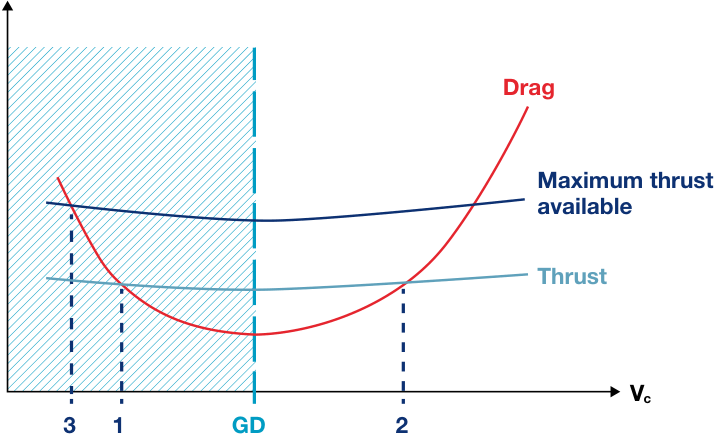
Above GD, the drag and thrust required to maintain speed increase with the speed
-
Below GD, the drag and thrust required to maintain speed increase with speed decrease (second regime) (fi g.2).
(fi g.2) Thrust curves and speed polar
Thrust / Drag
Section titled “Thrust / Drag”Region of reversed command (second regime)
Given: - altitude - temperature - weight - thrust
FIRST OR SECOND REGIME?
Section titled “FIRST OR SECOND REGIME?”At a given altitude, temperature, weight and thrust, fi gure 2 shows 2 points of equilibrium where the thrust precisely compensates for the drag (thrust = drag) and stabilized level fl ight is possible: point 1 (where VC is lower than GD) and point 2 (where VC is higher than GD). Let’s have a closer look at the aircraft behaviour if the speed is moving away from these speeds:
-
Point 2 is a stable equilibrium: in cruise, when the aircraft fl ies at this point 2, the airspeed is stabilized. Small variations of airspeed will naturally be compensated for and the aircraft will return to point 2. At point 2, the aircraft fl ies in the fi rst regime.
-
If a disturbance increases the aircraft’s speed above point 2, then the drag increases. Consequently, the aircraft will decelerate back to the equilibrium point 2.
-
If a disturbance reduces the aircraft’s speed below point 2, then the drag decreases. This generates acceleration and the aircraft’s speed will naturally increase back to the equilibrium point 2.
-
Point 1 is an unstable equilibrium: at this point, the aircraft fl ies in the second regime.
-
If a disturbance increases the aircraft’s speed above point 1, the drag reduces; therefore the aircraft will continue to accelerate until point 2.
-
If a disturbance reduces the aircraft’s speed below point 1, then the drag becomes increasingly higher. If no action is taken, the aircraft will be naturally induced into a continuous deceleration.
-
To stop the deceleration and be able to accelerate again, two scenarii are possible:
-
When speed reduces below point 1 and remains higher than point 3: if maximum thrust available is applied, then the aircraft can accelerate.
-
When speed reduces below point 3: there is no thrust margin available to accelerate while maintaining a stabilized level fl ight. Then the only way to stop the deceleration is to lose altitude in order to accelerate beyond point 3.
To sum up:
-
Faster than GD, the aircraft fl ies in the fi rst regime: it is stable with regards to speed.
-
Slower than GD, the aircraft fl ies in the second regime: it is unstable with regards to speed.
What are the operational implications of fl ying below GD?
Section titled “What are the operational implications of fl ying below GD?”Point 3 is not displayed on the PFD point 3 and eventually in a continuous airspeed scale. Only GD is shown. deceleration.
The higher the aircraft, the lower the maximum thrust available. This means that at high altitude, close to REC MAX (RECommended MAXimum altitude), point 3 and GD are close to each other because the thrust margin is small. Therefore fl ying below GD in level fl ight could easily drive the aircraft slower than
Consequently, in clean confi guration in cruise, the crew should not fl y below GD.
Exceptionally, if flight slightly below GD is required for some reason, then vigilant monitoring is necessary to ensure that further uncommanded speed reductions are immediately checked and recovered from.
GD IN A NUTSHELL Do not fl y below GD in cruise.
PROCEDURES
Section titled “PROCEDURES”Control your speed… in cruise
HOW IS THE REC MAX (RECOMMENDED MAXIMUM ALTITUDE) COMPUTED?
Section titled “HOW IS THE REC MAX (RECOMMENDED MAXIMUM ALTITUDE) COMPUTED?”Looking more closely at the exact conditions limiting the altitude where a subsonic aircraft can safely fl y at, these can range from aerodynamic limitations to propulsion and certifi cation limitations.
REC MAX is the upper cruise limit:
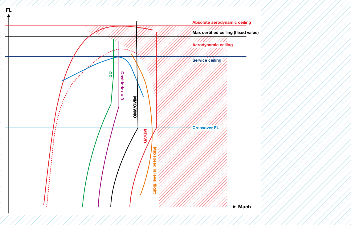
Section titled “REC MAX is the upper cruise limit:”REC MAX = Min [Service ceiling; Aerodynamic ceiling; Max certifi ed ceiling]
Section titled “REC MAX = Min [Service ceiling; Aerodynamic ceiling; Max certifi ed ceiling]”The schematic below applies to a heavy aircraft, which has a ceiling lower than the maximum certifi ed one.
-
This curve provides a safety maneuver margin against the Stall limit curve.
-
At low Mach, it starts at 1.23 x VS1g.
-
At higher Mach, it corresponds to buffet onset of 1.3g (corresponding to 40° of bank angle in level fl ight). This curve lowers with weight increase.
Aerodynamic ceiling (increases with weight decrease).
-
Service curve, corresponding to the propulsion capacity of the aircraft’s engines to maintain + 300ft/ minute at a constant Mach.
-
This curve increases with weight decrease and with static temperature decrease.
-
Service ceiling (increases with weight decrease or temperature decrease).
-
Maximum speed in level fl ight (in stable weather conditions with maximum thrust available in use)
-
Inaccessible domain (drag exceeds thrust), except if the aircraft is being subject to extreme weather conditions or enters a steep dive with maximum thrust.

On Airbus aircraft, the REC MAX is always limited by the service ceiling or the certifi ed ceiling; with the exception of A319 CJ aircraft and some versions of A340-500/600 aircraft at heavy weights.
The following graph gives an illustrative example of the above theoretical curves for an A320. This graph is used by the FMS to determine REC MAX.
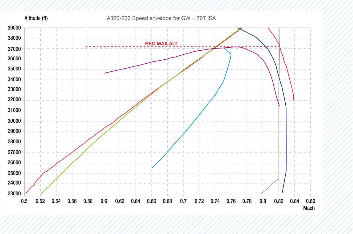
Buffet (1,3g) Vz 300 ft/min
VMO/MMO VMAX level at Max CLB
Econ speed CI = 0
CI = 0 (Cost Index 0) is the point that gives the maximum rate of climb at a steady Mach.
PROCEDURES
Section titled “PROCEDURES”Control your speed… in cruise
Limit speeds
Section titled “Limit speeds”For a given weight, each aircraft has a minimum selectable speed (VLS) and maximum speed (VMAX) at a particular altitude. At the cruise altitude, there
VLS: Lowest Selectable speed
Section titled “VLS: Lowest Selectable speed”Defi nition
Section titled “Defi nition”VLS is the lowest selectable speed with A/THR engaged. Even if the target speed is below VLS, the A/THR will continue to target VLS.
needs to be a safe margin in relation to these lowest and highest speeds, before the fl ight envelope protections activate.
VLS is indicated by the top of the amber line on the PFD speed scale (fi g.3).
How is VLS determined?
Section titled “How is VLS determined?”GD and VLS both depend on the aircraft weight, therefore these speeds will be wrong if the ZFW entered in the FMS is wrong.
Weight (ZFW) inserted in the FMS during fl ight preparation).
VLS is a characteristic speed computed by the AFS as a function of the aircraft weight (dependent on the Zero Fuel
VLS = 1.23 VS1g when in clean confi guration
Where:
VS1g is the stall speed demonstrated by fl ight tests.
Note: the 1.23 factor is applicable to fl y-by-wire aircraft (1.3 for the others).
This formula means that VLS is higher since speed brakes extension when the speed brakes are extended, increases VS1g.
What are the operational implications of not respecting VLS?
Section titled “What are the operational implications of not respecting VLS?”Deliberately flying below VLS could aircraft, or expose the aircraft to a either lead to an activation of the Anglestall if it is not protected, i.e. fl ying in a Of-Attack protection on a protected degraded law.
VLS IN A NUTSHELL.
VLS is the slowest speed the AFS lets you fl y in normal law.
V MO /M MO : Maximum Operating speed/Mach number
Section titled “V MO /M MO : Maximum Operating speed/Mach number”Definition
Section titled “Definition”In cruise, in clean confi guration, VMO/MMO is the higher limit of the aircraft speed envelope.
It is indicated by the lower end of the red and black strip along the PFD speed scale (fi g.4).
THE CROSSOVER ALTITUDE
Section titled “THE CROSSOVER ALTITUDE”Aircraft normally fl y at an optimal IAS until they reach their optimal climb/ cruise Mach. This transition between airspeed and Mach occurs at a point called the “crossover altitude” (usually between FL250 and FL300 depending on the aircraft type). When the aircraft climbs to the crossover altitude at a constant IAS, Mach increases. The opposite happens when in descent to the crossover altitude, at a constant Mach. Then the IAS increases. At altitudes above the crossover altitude, pilots will fly a Mach number instead of an IAS because it then becomes the most meaningful parameter.
Different phenomena exist according to the speed or Mach the aircraft fl ies at. The aerodynamic world can therefore be split into two areas: low and high Mach numbers.
- At high Mach number, when accelerating beyond MMO, slight vibrations may appear. These are vibrations due to unsteady early
onset shock waves developing on the wings upper surface. These shock waves significantly worsen the drag and can alter the aircraft’s controllability. But this phenomenon has nothing to do with buffet announcing lack of lift to come or an approaching stall. Airbus airplanes operated up to VD/MD are not exposed to the so-called high speed buffet.
• At high Indicated AirSpeed (IAS), the main threat to the aircraft structural integrity lies in the dynamic pressure exerted by air on the structure. Aircraft controllability remains optimum as long as the Mach number is not too high.
In practice, the aircraft is designed to be safe up to Mach/speeds well above VMO/MMO. Indeed, according to certifi cation requirements the aircraft must be safe to fl y up to the design limit speed/Mach number VD/MD. In other words, up to VD/MD, the aircraft remains controllable and free of any fl utter.
How is VMO/MMO determined?
Section titled “How is VMO/MMO determined?”VMO/MMO is established with regards to the aircraft’s structural limits and it provides a margin to the design limit speed/Mach number VD/MD. VD/MD must be suffi ciently above VMO/MMO to make it highly improbable that VD/ MD will be inadvertently exceeded in commercial operations. Several certifi cation criteria exist. As a result,
on Airbus aircraft, MD is usually equal to MMO + 0.07 and VD approximately equal to VMO + 35 kt.
The applicable VMO/MMO are indicated in each Aircraft Flight Manual. For example, VMO/MMO and VD/MD are given in the following table.
| Aircraft type | VMO(kt) | MMO | VD (kt) | MD |
|---|---|---|---|---|
| A350 | 340 | 0.89 | 375 | 0.96 |
| A380 | 340 | 0.89 | 375 | 0.96 |
| A330/A340 | 330 | 0.86 | 365 | 0.93 |
| A320 Family | 350 | 0.82 | 381 | 0.89 |
| A300-600 | 335 | 0.82 | 395 | 0.89 |
| A310 | 360 | 0.84 | 420 | 0.90 |
PROCEDURES
Section titled “PROCEDURES”Control your speed… in cruise
At low altitudes, the threat of exceeding VMO by a significant amount is real and it can dramatically affect the integrity of the aircraft’s structure.
of the maneuver performed by test pilots to determine these speed and Mach.
These concepts involve understanding the maximum structural speed and Mach of the aircraft VD/MD.
VD is a Calibrated Air Speed (CAS). During test flights, VD/MD are reached by test pilots with the objective to demonstrate that the aircraft structural integrity is not put at stake at these speeds, and that the aircraft remains safely recoverable at all times. The article “High-altitude manual flying” that was published in the 20[th] issue of this magazine provides a good explanation
Key points to remember are:
-
Reaching VD is much easier than reaching MD,
-
At high altitude, reaching the aircraft’s structural limit is almost impossible,
-
At lower altitudes (i.e. below the crossover altitude), reaching VD is possible because the available thrust is higher, and drag due to Mach is lower.
What are the operational implications of not respecting VMO/MMO?
Section titled “What are the operational implications of not respecting VMO/MMO?”The JAR / FAR 25 rule dictates that VMO or MMO may not be deliberately exceeded in any regime of flight. The parameter VMO/MMO basically sets upper boundaries to the aircraft speed envelope.
- At lower altitudes, exceeding VMO by a significant amount is a real threat and can dramatically affect the integrity of the aircraft’s structure.
Although intentional VMO/MMO exceedance cases are rare, this limit speed can typically be overshot when the aircraft is subject to unusual wind and/ or temperature gradient. Prevention is therefore essential.
Crews should keep in mind that
- At high altitude, whilst it is important to always respect MMO, a slight and temporary Mach increase above that value will not lead the aircraft into an immediate hasardous situation.
VMO/MMO IN A NUTSHELL
VMO/MMO is the “never to exceed” speed.
Flight envelope protection speeds: V** α PROT and V α **MAX
Section titled “Flight envelope protection speeds: V** α PROT and V α **MAX”Definition
Section titled “Definition”V α PROT is the speed corresponding to the maximum Angle-Of-Attack (AOA) at which Alpha Protection becomes active. It is only displayed in normal law and corresponds to the top of the black and amber strip along the PFD speed scale (fig.5).
In practice, the AOA value of the Alpha Protection decreases as the Mach number increases. When the AOA value of the Alpha Protection decreases, the Alpha Protection strip on the PFD moves upward.
V α MAX is the maximum Angle-Of-Attack speed. It is the speed corresponding to the maximum Angle-Of-Attack the aircraft can fly at in normal law. It corresponds to the top of the solid red strip along the PFD speed scale (fig.5).
α MAX is a function of the Mach number: it decreases when the Mach increases (fig.6).
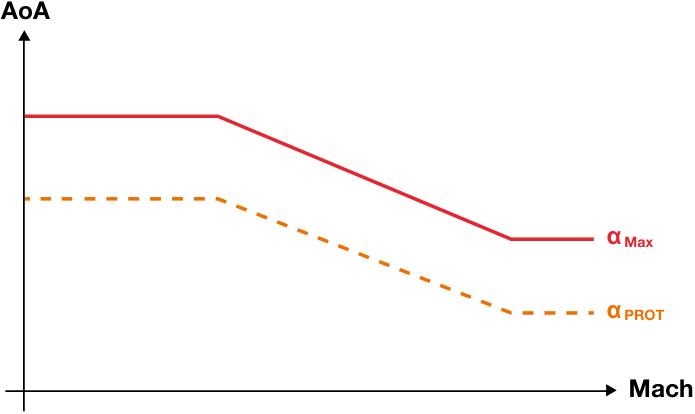
Evolution with the Mach number of the[AOA value triggering the α ] Protection and α Maximum, in clean confi guration
How are V** α PROT and V α **MAX determined?
Section titled “How are V** α PROT and V α **MAX determined?”Contrary to GD and VLS, V α PROT and aircraft speed would be if it fl ew at an V α MAX are not based on the aircraft Angle-Of-Attack (AOA) equal to α PROT weight, as inserted in the FMS during (resp. α MAX). In fact, both speeds are fl ight preparation through the ZFW. calculated on the basis of the aircraft longitudinal equilibrium equation, along V α PROT (resp. V α MAX) as displayed on with the actual aircraft speed and AOA. the PFD is a prediction of what the
V α PROT = Vc x √( α - α 0)/( α PROT- α 0))
V α PROT and V α MAX are not based on the aircraft weight.
Where:
α 0 is the AOA for a Lift Coeffi cient (CL) equal to 0. VC is the calibrated airspeed (CAS) α is current AOA
Section titled “α 0 is the AOA for a Lift Coeffi cient (CL) equal to 0. VC is the calibrated airspeed (CAS) α is current AOA”On the A320 Family, V α PROT and V α MAX can have different numerical values on both PFDs because VC comes from different sources for left and right PFDs.
On A330/A340, A350 and A380 Families, V α PROT and V α MAX have the same numerical values on both PFDs.
|---|---|---|
PROCEDURES
Section titled “PROCEDURES”Control your speed… in cruise
When fl ying in a degraded law, increasing the AOA would directly expose the aircraft to stall, like on any conventional aircraft.
In order to avoid a fl uctuating V α PROT and V α MAX display, AOA and VC values are fi ltered so that fast AOA variations (for example during turbulence) do not pollute the PFD speed scale.
As a result of this fi ltering, a little delay can be observed; therefore during a dynamic maneuver, the aircraft may enter into a protection law with the IAS not yet below the displayed V α PROT.
What are the operational implications of flying below V** α **PROT?
Section titled “What are the operational implications of flying below V** α **PROT?”At any time during cruise, the actual AOA is compared to α PROT (or α MAX) in real time. The difference of AOA is then converted to speed and applied on each PFD: the delta between current speed and V α PROT (or V α MAX) represents the actual margin against α PROT (or α MAX) (fi g.7).
threshold would immediately trigger the high AOA protection, thus resulting in a nose down pitch rate ordered by the fl ight control laws. Further increasing the AOA by maintaining full back stick would eventually result in reaching the α MAX threshold. When fl ying in a degraded law, increasing the AOA would directly expose the aircraft to stall.
In normal law, on a protected aircraft, exceeding the AOA value of the α PROT
Cruise speeds in a nutshell
Section titled “Cruise speeds in a nutshell”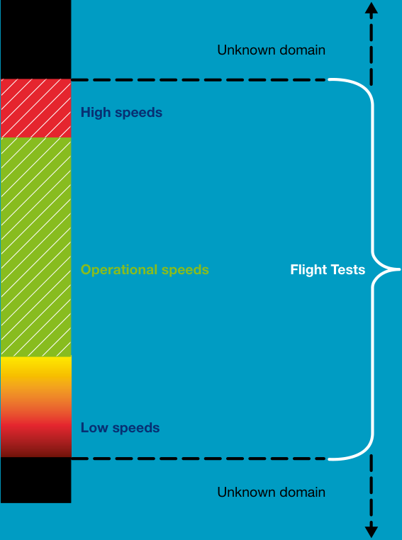
MANAGING YOUR CRUISE: SPEED EXCURSIONS OPERATIONAL RECOMMENDATIONS
Section titled “MANAGING YOUR CRUISE: SPEED EXCURSIONS OPERATIONAL RECOMMENDATIONS”Understanding how the aircraft’s speed envelope is defined is essential to speed excursion avoidance. Knowing the threats to airspeed and the tools at the crew’s disposal to tackle them is another part of that goal. This includes knowing exactly which information should be looked at and how, with the aim to acquire the best possible situational awareness and be able to avoid an overspeed (i.e. VMO/MMO exceedance) or a speed decay (i.e. reaching below VLS), and react wisely in case of an actual encounter.
Reading the first section of this article and understanding how VMO/MMO and VD/MD are determined highlighted that:
At high altitude, reaching the aircraft’s structural limit Mach number is almost impossible (except in a steep dive with maximum thrust); therefore at high altitude, flying at high Mach number should not be viewed as the biggest threat to the safety of flight. Conversely, flying too slow (below Green Dot) at high altitude can lead to progressive reductions in speed until the protections are triggered. Should this speed reduction take place in a degraded law, it could lead to a loss of control due to stall. At and near the performance altitude limit of the aircraft, the range of available speeds between Green Dot and MMO will be small. Speed decay at high altitude must be avoided as a result.
• At lower altitudes (i.e. below the crossover altitude), too large a speed decay can similarly lead a non protected aircraft (i.e. flying in a degraded law) to enter a stall. Nevertheless, at low altitude, the available envelope is greater and the thrust margin is much higher, thus providing flight crews a greater ability to safely control the airspeed and recover from a speed decay. On the other hand, at low altitude, reaching VMO and VD is possible; therefore high speed should be viewed indeed as a significant threat to the safety of flight.
This chapter offers pilots background knowledge of available prevention means in order to properly manage the main threats to the airspeed, and eventually prevent an overspeed or a speed decay thanks to anticipation and use of dedicated procedures.
The biggest threat to the safety of flight both at high and low altitude relates to speed decay.
How to anticipate a speed excursion
Section titled “How to anticipate a speed excursion”Clearly flight crews are expected to be able to rapidly scan the essential and relevant parameters, in every situation, in every flight phase, including dynamic
ones. In most cases, speed excursion situations are due to rapid wind and temperature variations/evolutions.
PROCEDURES
Control your speed… in cruise
Gaining a good awareness of weather
Section titled “Gaining a good awareness of weather”Weather is an important factor that influences aircraft performances. Be it a local flight or a long haul flight, decisions based on weather can dramatically affect the safety of the flight. As it turns out, the first external threat to airspeed comes from weather disturbances, such as turbulent areas that can lead to significant speed changes.
Common sense generally makes pilots avoid those areas; however, they sometimes end up in a situation where some solid turbulence is encountered, when dodging thunderstorms for example. At this point, the airspeed begins to fluctuate, thus making speed exceedance or speed decay more likely. Such situations need to be planned ahead and as far as possible, avoided through regular scanning of weather conditions and flight path adaptation.
The first key to preventing speed excursion events is gaining awareness of the available weather predictions along the forecasted route. Before take-off, the weather briefing has to be as complete as possible. Pilots should check weather reports at alternate and destination airports and, depending on the weather context, this information needs to be updated in flight as often as necessary. Weather information can be communicated either by the Air Traffic Controllers or by the other crews flying in the area. Once airborne, the weather radar is one powerful tool to help the crew make sound weather related decisions to avoid adverse weather and turbulence areas.
Altitude and wind gradients: the main contributing factors
Section titled “Altitude and wind gradients: the main contributing factors”The nearer the aircraft is to the REC MAX FL, the smaller the thrust margin.
On aircraft with no failure, and the A/THR engaged or the MAX CLB thrust applied in manual mode, a continuous speed decay during cruise phase may be due to:
-
A large and continuous increase in tailwind or decrease in headwind, in addition to an increase in the Outside Air Temperature (OAT), that results in a decrease of the REC MAX FL, or
-
A large or prolonged downdraft, when the flight crew flies (parallel and) downwind in a mountainous area, due to orographic waves. The downdraft may have a negative vertical speed of more than 500 ft/ min. Therefore, if the aircraft is in a downdraft, the aircraft must climb in
order to maintain altitude, and the pitch angle and the thrust values increase. Without sufficient thrust margin, the flight crew may notice that aircraft speed decays, but the REC MAX FL is not modified.
The flight crew must be aware that at high altitude, the thrust margin (difference between the thrust in use and the maximum available thrust) is limited. The maximum available thrust decreases when there is an increase in altitude and/or outside temperature. The REC MAX FL indicated in the FMS decreases when the OAT increases. The nearer the aircraft is to the REC MAX FL, the smaller the thrust margin.
Preventing a speed decay: detecting the phenomenon
Section titled “Preventing a speed decay: detecting the phenomenon”At any altitude, decreasing the speed too much will certainly lower the aircraft’s level of energy and decrease margins for maneuvering, thus potentially leading to a loss of control due to stall with an aircraft flying in a degraded law. It is important to understand and detect
signs of a significant speed decay in order to be able to recover.
When speed decreases, pilots should be attentive to their speed trend vector as displayed on the PFD and take action if an unfavourable speed trend develops in order to remain above GD.
If the speed decreases further, then the Angle-Of-Attack (AOA) must be increased in order to increase the lift coeffi cient CL, which keeps the forces balanced. However, it is not possible to indefi nitely increase the AOA.
vibrations. Buffet is a clear sign of an approaching stall or even of the stall itself depending on its severity: it is created by airfl ow separation and is a function of AOA (fi g.8).
- At buffet initiation, the pilot starts to feel airfl ow separation on wings upper surface.
As per basic aerodynamic rules, the lift coeffi cient CL increases linearly with the AOA up to a point where the airfl ow separates from the upper wing surface. If the AOA continues to increase, the point of airfl ow separation is unstable and rapidly fl uctuates back and forth. Consequently, the pressure distribution along the wing profile changes constantly and also changes the lift’s position and magnitude. This effect is called buffeting and is evidenced by
-
The buffet onset corresponds by defi nition to 1.3g (corresponding to 40° of bank angle in level fl ight).
-
The “deterrent buffet” is so strong that any pilot will feel he/she needs to leave these buffet conditions. It corresponds to one of the defi nitions of stall.
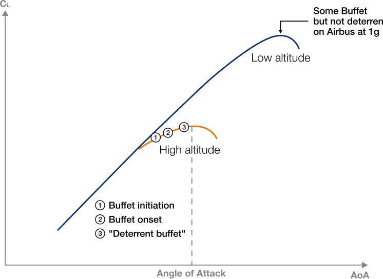
When the AOA reaches a maximum value, the separation point moves further forward on the wing upper surface and almost total fl ow separation of the upper surface of the wing is achieved: this phenomenon leads to a signifi cant loss of lift, referred to as a stall. Incidentally, stall is not a pitch issue and can happen at any pitch value.
These conditions should be avoided thanks to anticipation and regular scanning of both the weather conditions along the fl own route, and of the speed trend on the PFD. Nevertheless, these conditions might be approached unintentionally. As soon as any stall indication is recognized – be it the aural warning “STALL + CRICKET” or buffet – the aircraft’s trajectory becomes diffi cult to control and the “Stall recovery” procedure must be applied immediately.
(fi g.8)
Section titled “(fi g.8)”AOA effect on lift
Stall is not a pitch issue and can happen at any pitch. Stalling is only an AOA issue.
PROCEDURES
Section titled “PROCEDURES”Control your speed… in cruise
A video illustrating buffet is presented in the tablet application of Safety fi rst for this issue.
Approach to stall
Section titled “Approach to stall”-
Indications - Artifi cial stall warnings
-
Indications - Artifi cial stall warnings

-
Some natural stall warning indications - Natural stall warnings may be present - Buffeting
-
Lack of pitch authority
-
Lack of roll control
-
Progressive airfl ow separation
-
Inability to arrest descent
-
Airfl ow separated from wing
-
Trajectory controllable with decreasing margin for maneuvering
-
Trajectory no longer controllable
Preventing and recovering from a VMO/MMO exceedance: dedicated procedures
Section titled “Preventing and recovering from a VMO/MMO exceedance: dedicated procedures”Using dedicated procedures
Section titled “Using dedicated procedures”As soon as an unfavourable speed following the operating techniques trend develops, pilots must take action and recommendations detailed in the and prevent a speed exceedance, OVERSPEED PREVENTION procedure.
DID YOU KNOW
Section titled “DID YOU KNOW”On the A320 Family, speed brakes extension and retraction rates at high Mach/Vc are roughly twice as slower Auto Pilot (AP) engaged compared with AP disengaged. As a consequence, if used to avoid a VMO/MMO exceedance, crew should keep this in mind to retract them timely in order to avoid reducing their speed below GD. This is particularly true when fl ying close to REC MAX.
In most cases, the use of this OVERSPEED PREVENTION procedure will effectively prevent exceeding V MO/M MO. Nevertheless, due to system design and limited authority, this may not be sufficient. For this reason, a OVERSPEED RECOVERY procedure was developed as well and implemented in the FCOM /QRH.
The OVERSPEED warning is triggered when the speed exceeds VMO + 4 kt or MMO + 0.006, and lasts until the speed is below VMO/MMO. In this case, the fl ight crew must apply the OVERSPEED RECOVERY procedure.
Maintaining the aircraft after a VMO/MMO exceedance
Section titled “Maintaining the aircraft after a VMO/MMO exceedance”The flight crew must report any type of overspeed event (i.e. if the OVERSPEED warning is triggered). Indeed, in case of an overspeed, an inspection of the aircraft structure may be required. Indeed, when an overspeed event occurs, the aircraft may experience a high load factor. Only an analysis of
flight data allows to tell whether or not an inspection is required.
This supports the crucial need for flight crews experiencing an overspeed to report it! Then maintenance and engineering teams will judge whether or not further inspection is needed.

Any type of overspeed must be reported by the flight crew. Only an analysis of flight data allows to tell whether or not an inspection is required.
In cruise, the aircraft airspeed might not be the desired one at all times. The aircraft may encounter adverse weather and turbulences, or even winds, which all have a direct impact on the airspeed. For this reason, flight crews must remain vigilant at all times and anticipate the main threats to the airspeed by planning ahead and communicating.
In practice, once the aircraft is airborne, pilots must be fully cognisant of the airspeed as well as the speed trends at all times in flight. In case of need, the FCOM/QRH and FCTM provide procedures and adequate guidelines to prevent and to recover from a speed excursion, and react wisely to any variation of airspeed. They are worth being thoroughly read and understood in advance.
DID YOU KNOW
Section titled “DID YOU KNOW”To know more about speeds, read our brochure “Getting to grips with aircraft performance”, available on AirbusWorld.
006 Safety First #21 | 2016年1月 程序
Section titled “006 Safety First #21 | 2016年1月 程序”控制您的速度……在巡航阶段
这是“控制您的速度”系列文章的第三篇,前两篇分别刊登于本刊第18期和第20期。在本文中,我们的飞机以光洁形态飞行,处于巡航阶段。主要目标是管理空速威胁,避免速度偏差。
洛林·菲利普·德·博杜斯·卡斯塔涅 试飞员 标准与安全管理
从技术角度讲,巡航包括航向改变和飞机系统监控(尤其是燃油),此时空速和高度相对恒定。巡航结束于飞机接近目的地、开始下降准备着陆之时。
在此飞行阶段,速度监控与控制至关重要,以确保飞机始终在经认证的飞行包线内飞行,并妥善管理任何空速威胁。
本文不会深入探讨优化巡航阶段飞机性能的挑战,而是旨在阐明巡航期间空速面临的现有威胁,以及管理这些威胁的最佳做法。机组人员在规划巡航时做出正确的速度和飞行高度层选择,需要对速度偏差保持警惕,并在需要时能够进行修正。
巡航管理:了解速度
Section titled “巡航管理:了解速度”巡航速度往往由性能和燃油消耗考量所驱动;然而,空中交通或天气因素有时会介入,要求修改最优巡航方案。无论机组人员为最佳优化飞行做出何种决定,都需要始终了解适用的限制速度和机动速度。为了在飞机经认证的飞行包线内安全管理巡航阶段,一些特征速度可作为飞行机组监控飞机实际速度的参考。那么,具体应监控哪些速度?这些速度意味着什么?如果忽视它们会发生什么?
本文所包含的系统描述和信息主要涉及电传操纵飞机。然而,速度管理的建议适用于所有飞机。
认证和运营飞行飞机需要使用许多速度。对于每个航班,适用的特征速度由飞机自动飞行系统(Auto Flight Systems,飞行管理系统(FMS)、飞行引导(FG)和飞行包线(FE))自动计算,并显示在主飞显示器(PFD)的空速刻度上。它们是非常有用的目标机动和限制参考速度,可安全引导飞行员在巡航阶段做出导航决策。
我们的目标是阐明空客发布的所有关于巡航阶段速度监控建议背后的设计和运营考量。
控制您的速度……在巡航阶段
绿点速度已在先前专门介绍爬升阶段的文章中介绍过。然而,在巡航阶段也需要记住这一速度,因为它在PFD空速刻度上是清晰可见的参考速度。
我们将看到下文阐述为什么飞行员在巡航时不应常规低于绿点速度飞行。
因此,下文提供了绿点定义的回顾,以及在巡航中低于绿点速度飞行的后果。
绿点速度(GD):最佳升阻比速度
Section titled “绿点速度(GD):最佳升阻比速度”绿点速度是光洁形态下单发停车运行速度。它对应于光洁形态下单发失效时能够获得最佳爬升梯度的速度。在所有发动机工作的情况下,绿点速度可提供最佳升阻比的估计速度。
绿点速度是如何确定的?
Section titled “绿点速度是如何确定的?”绿点速度由自动飞行系统(AFS)计算,基于飞机重量(在飞行准备阶段输入FMS的无燃油重量(ZFW))。绿点公式的设定使得在给定高度、马赫数和飞机重量下,以光洁形态单发失效时,所得到的空速能够提供最佳升阻比。
它以PFD速度刻度上的绿点符号表示,仅当缝翼/襟翼控制手柄处于“0”(光洁)位置且起落架未压缩时才会显示 (图1)。
在巡航中:
-
高于绿点速度时,维持速度所需的推力和阻力随速度增加而增加
-
低于绿点速度时,维持速度所需的推力和阻力随速度减小而增加(第二状态) (图2)。
(图2) 推力曲线和速度极曲线
推力 / 阻力
Section titled “推力 / 阻力”反向指令区(第二 regime)
已知条件: - 高度 - 温度 - 重量 - 推力
第一还是第二 REGIME?
Section titled “第一还是第二 REGIME?”在给定的高度、温度、重量和推力条件下,图2显示了2个平衡点,在这两个点上推力恰好补偿了阻力(推力=阻力),可以维持稳定的平飞:点1(VC 低于 GD)和点2(VC 高于 GD)。让我们仔细观察当速度偏离这些点时飞机的行为:
-
点2是一个稳定的平衡点:在巡航中,当飞机在这个点2飞行时,空速是稳定的。小幅的空速变化会自动得到补偿,飞机将回到点2。在点2,飞机处于第一 regime。
-
如果一个扰动使飞机速度增加到超过点2,则阻力增加。因此,飞机会减速回到平衡点2。
-
如果一个扰动使飞机速度降低到低于点2,则阻力减小。这会产生加速,飞机速度将自然增加回到平衡点2。
-
点1是一个不稳定的平衡点:在这一点,飞机处于第二 regime。
-
如果一个扰动使飞机速度增加到超过点1,阻力减小;因此飞机会持续加速直到点2。
-
如果一个扰动使飞机速度降低到低于点1,则阻力变得越来越高。如果不采取行动,飞机会自然地被引入持续减速。
-
为了停止减速并能够再次加速,存在两种可能的情景:
-
当速度降低到点1以下但保持在点3以上时:如果施加最大可用推力,飞机会能够加速。
-
当速度降低到点3以下时:在保持稳定平飞的同时没有可用的推力余量来加速。因此,停止减速的唯一方法是失去高度以加速超过点3。
总结:
-
快于 GD 时,飞机处于第一 regime:相对于速度是稳定的。
-
慢于 GD 时,飞机处于第二 regime:相对于速度是不稳定的。
在 GD 以下飞行的操作影响是什么?
Section titled “在 GD 以下飞行的操作影响是什么?”点3不会显示在 PFD 上,点3最终会在一个连续的空速刻度上显示。只有 GD 会被显示。减速。
飞机飞得越高,可用最大推力越低。这意味着在高高度,接近 REC MAX(建议最大高度)时,点3和 GD 彼此接近,因为推力余量很小。因此,在平飞中低于 GD 飞行可能会轻易地使飞机比点3更慢。
因此,在巡航中以光洁构型飞行时,机组不应在 GD 以下飞行。
例外地,如果因某种原因需要略微低于 GD 飞行,则需要进行警惕性监控以确保任何进一步的非指令性速度降低被立即检查并改出。
GD 简述 在巡航中不要在 GD 以下飞行。
在巡航中控制您的速度……
REC MAX(建议最大高度)是如何计算的?
Section titled “REC MAX(建议最大高度)是如何计算的?”更仔细地观察限制亚音速飞机可以安全飞行的高度的确切条件,这些可以从气动限制到推进和认证限制。
REC MAX 是上部巡航限制:
Section titled “REC MAX 是上部巡航限制:”REC MAX = Min [服务天花板;气动天花板;最大认证天花板]
Section titled “REC MAX = Min [服务天花板;气动天花板;最大认证天花板]”下图适用于天花板低于最大认证高度的重型飞机。
-
该曲线为失速限制曲线提供了安全机动余量。
-
在低马赫数时,它从 1.23 x VS1g 开始。
-
在较高马赫数时,它对应于 1.3g 的抖振边界(在平飞中相当于40°倾斜角)。该曲线随重量增加而降低。
气动天花板(随重量减小而增加)。
-
服务曲线,对应于飞机发动机以恒定马赫数维持 + 300ft/分钟的推进能力。
-
该曲线随重量减小或静态温度降低而增加。
-
服务天花板(随重量减小或温度降低而增加)。
-
平飞中的最大速度(在稳定天气条件下使用最大可用推力)
-
不可达区域(阻力超过推力),除非飞机处于极端天气条件或以最大推力进入急剧俯冲。
在 Airbus 飞机上,REC MAX 始终受服务天花板或认证天花板限制;A319 CJ 飞机和某些 A340-500/600 飞机在重载时除外。
下图给出了上述理论曲线在 A320 上的示例说明。该图被 FMS 用来确定 REC MAX。
抖振(1.3g) Vz 300 ft/min
VMO/MMO VMAX 平飞上限 最大爬升
经济速度 CI = 0
CI = 0(成本指数 0)是在稳定马赫数下给出最大爬升率的点。
控制您的速度……在巡航阶段
对于给定的重量,每架飞机在特定高度都有一个最小可选速度(VLS)和最大速度(VMAX)。在巡航高度,在飞行包线保护启动之前,需要与这些最低和最高速度保持安全余量。
VLS:最小可选速度
Section titled “VLS:最小可选速度”VLS是A/THR接通时的最小可选速度。即使目标速度低于VLS,A/THR将继续以VLS为目标。
VLS由PFD速度刻度上琥珀色线条的顶端指示**(图3)**。
VLS是如何确定的?
Section titled “VLS是如何确定的?”GD和VLS都取决于飞机重量,因此如果在FMS中输入的ZFW错误,这些速度也会错误。
VLS是一种特性速度,由AFS根据飞机重量计算得出(取决于零燃油重量(ZFW),即在飞行准备阶段在FMS中输入的重量)。
VLS = 1.23 VS1g(处于光洁构型时)
其中:
VS1g是飞行测试演示的失速速度。
注:1.23系数适用于电传操纵飞机(其他飞机为1.3)。
此公式意味着,当减速板伸出时,VS1g增加,因此VLS更高。
不遵守VLS会产生哪些运行影响?
Section titled “不遵守VLS会产生哪些运行影响?”故意低于VLS飞行可能导致飞机失速保护启动(即在降级法则下飞行时),或使飞机面临未受保护的失速攻角风险。
VLS简要总结。
VLS是AFS在正常法则下允许您飞行的最慢速度。
V MO/M MO:最大运行速度/马赫数
Section titled “V MO/M MO:最大运行速度/马赫数”在巡航阶段,处于光洁构型时,VMO/MMO是飞机速度包线的上限。
它由PFD速度刻度上红黑条带的下端指示**(图4)**。
飞机通常以最佳指示空速(IAS)飞行,直到达到最佳爬升/巡航马赫数。空速和马赫数之间的转换发生在称为“交叉高度”的点(通常在FL250和FL300之间,取决于飞机类型)。当飞机以恒定IAS上升至交叉高度时,马赫数增加。相反,当以恒定马赫数下降至交叉高度时,IAS增加。在交叉高度以上,飞行员将使用马赫数而非IAS飞行,因为此时马赫数成为最有意义的参数。
根据飞机所处的速度或马赫数,存在不同的现象。因此,空气动力世界可分为两个区域:低马赫数和高马赫数。
-
在高马赫数时,当加速超过MMO时,可能会出现轻微振动。这些振动是由于在机翼上表面形成的不稳定早期 onset激波引起的。这些激波显著增加阻力,并可能改变飞机的可控性。但这种现象与宣布即将失速或接近失速的抖振无关。空客飞机运行至VD/MD时不会暴露于所谓的高速抖振中。
-
在高指示空速(IAS)时,对飞机结构完整性的主要威胁在于空气对结构施加的动压。只要马赫数不太高,飞机可控性保持最佳。
实际上,飞机设计可承受远高于VMO/MMO的速度/马赫数。事实上,根据认证要求,飞机必须能够安全飞行至设计限制速度/马赫数VD/MD。换言之,在VD/MD以下,飞机保持可控且无任何颤振。
VMO/MMO是如何确定的?
Section titled “VMO/MMO是如何确定的?”VMO/MMO是根据飞机的结构限制建立的,它为设计限制速度/马赫数VD/MD提供了余量。VD/MD必须足够高于VMO/MMO,以使VD/MD在商业运行中被无意超过的可能性极低。存在若干认证标准。因此,
在空客飞机上,MD通常等于MMO + 0.07,VD大约等于VMO + 35 kt。
适用的VMO/MMO在每本飞机飞行手册中注明。例如,下表给出了VMO/MMO和VD/MD。
| 飞机类型 | VMO(kt) | MMO | VD (kt) | MD |
|---|---|---|---|---|
| A350 | 340 | 0.89 | 375 | 0.96 |
| A380 | 340 | 0.89 | 375 | 0.96 |
| A330/A340 | 330 | 0.86 | 365 | 0.93 |
| A320系列 | 350 | 0.82 | 381 | 0.89 |
| A300-600 | 335 | 0.82 | 395 | 0.89 |
| A310 | 360 | 0.84 | 420 | 0.90 |
控制您的速度……在巡航阶段
在低空,超出VMO相当多的威胁是真实存在的,可能会严重影响飞机结构的完整性。
这些概念涉及理解飞机的最大结构速度和马赫数VD/MD。
VD是校准空速(CAS)。在试飞期间,VD/MD由试飞员达到,目的是证明飞机结构完整性在这些速度下不会受到影响,并且飞机始终可以安全恢复。本杂志第20期发表的“高原人工飞行”一文对此作了很好的解释。
测试飞行员执行这些速度和马赫数的演示。
需要记住的要点是:
-
达到VD比达到MD容易得多,
-
在高空,达到飞机结构限制几乎是不可能的,
-
在较低高度(即低于交叉高度),由于可用推力更高且马赫阻力更低,可以达到VD。
不遵守 VMO/MMO 的运行影响是什么?
Section titled “不遵守 VMO/MMO 的运行影响是什么?”JAR/FAR 25 规则规定,在任何飞行状态下,VMO 或 MMO 不得被故意超过。VMO/MMO 参数本质上设定了飞机速度包线的上限边界。
- 在低空,超过 VMO 达到一定量是真正的威胁,可能会严重影响飞机结构的完整性。
虽然故意超过 VMO/MMO 的情况很少见,但当飞机遭遇异常风和/或温度梯度时,通常会超过该限制速度。因此,预防至关重要。
机组应牢记:
- 在高空,虽然始终遵守 MMO 很重要,但略微且暂时超过该值的马赫数增加不会使飞机立即陷入危险状态。
VMO/MMO 一览
VMO/MMO 是”永不得超过”的速度。
飞行包线保护速度:Vα PROT 和 Vα MAX
Section titled “飞行包线保护速度:Vα PROT 和 Vα MAX”Vα PROT 是对应于 α 保护生效时的最大迎角(AOA)速度。它仅在正常法则下显示,对应于 PFD 速度刻度上黑条和琥珀色条顶端的标记(图 5)。
实际上,α 保护的 AOA 值随马赫数增加而减小。当 α 保护的 AOA 值减小时,PFD 上的 α 保护条会向上移动。
Vα MAX 是最大迎角速度。它是飞机在正常法则下能以最大迎角飞行的速度,对应于 PFD 速度刻度上实心红色条顶端的标记(图 5)。
α MAX 是马赫数的函数:它随马赫数增加而减小(图 6)。
光洁构型下触发 α 保护的 AOA 值和 α MAX 随马赫数的变化
Vα PROT 和 Vα MAX 是如何确定的?
Section titled “Vα PROT 和 Vα MAX 是如何确定的?”与 GD 和 VLS 不同,Vα PROT 和 Vα MAX 不是基于飞机重量(如在飞行准备阶段输入 FMS 的 ZFW)计算得出。实际上,两个速度都是基于飞机纵向平衡方程计算的,沿 Vα PROT(相应地 Vα MAX)显示在 PFD 上的飞机速度是实际速度和 AOA 的预测值。
Vα PROT = Vc x √(α - α₀)/(α PROT - α₀))
Vα PROT 和 Vα MAX 不是基于飞机重量。
其中:
α₀ 是升力系数(CL)等于 0 时的 AOA。Vc 是校准空速(CAS)α 是当前 AOA
在 A320 系列飞机上,左侧和右侧 PFD 上的 Vα PROT 和 Vα MAX 可能显示不同数值,因为 Vc 来自左右 PFD 的不同数据源。
在 A330/A340、A350 和 A380 系列飞机上,左右 PFD 上的 Vα PROT 和 Vα MAX 具有相同的数值。
|---|---|---|
Control your speed… in cruise
当飞机在降级法则下飞行时,增加 AOA 会直接使飞机面临失速风险,就像在常规飞机上一样。
为了避免 Vα PROT 和 Vα MAX 显示出现波动,AOA 和 Vc 值被过滤处理,使得快速 AOA 变化(例如在颠簸期间)不会污染 PFD 速度刻度。
由于这种过滤处理,可能会观察到一点延迟;因此在动态机动期间,飞机可能会在 IAS 尚未降至显示的 Vα PROT 以下时就进入保护法则。
在α PROT以下飞行的运行影响是什么?
Section titled “在α PROT以下飞行的运行影响是什么?”在巡航过程中的任何时刻,实际AOA会与α PROT(或α MAX)进行实时比较。然后AOA差值会被转换为速度并显示在每个PFD上:当前速度与Vα PROT(或Vα MAX)之间的差值代表了相对于α PROT(或α MAX)的实际裕度 (图7)。
阈值会立即触发高AOA保护,从而产生由飞控法则指令的低头俯仰率。如果继续通过保持全拉杆来增加AOA,最终将导致达到α MAX阈值。当飞机在降级法则下飞行时,增加AOA会直接使飞机面临失速风险。
在正常法则下, 在受保护的飞机上,超过α PROT的AOA值会立即触发高AOA保护,从而产生由飞控法则指令的低头俯仰率。
巡航速度简述
Section titled “巡航速度简述”
管理您的巡航:速度偏移运行建议
Section titled “管理您的巡航:速度偏移运行建议”了解飞机速度包线是如何定义的是避免速度偏移的关键。了解空速威胁以及机组可用的应对工具是实现这一目标的另一部分。这包括准确了解应该查看哪些信息以及如何查看,目标是获得最佳的态势感知,并能够避免超速(即VMO/MMO超限)或速度衰减(即降至VLS以下),并在实际遇到时明智地做出反应。
阅读本文的第一部分并理解VMO/MMO和VD/MD是如何确定的,突出了以下几点:
在高高度,飞机结构极限马赫数几乎不可能达到(除非在大角度俯冲配合最大推力的情况下);因此在高高度,高马赫数飞行不应被视为对飞行安全的主要威胁。相反,在高高度飞行过慢(在绿点以下)可能导致速度逐渐降低直至触发保护。如果这种速度降低发生在降级法则下,可能导致因失速而失去控制。在接近飞机性能高度限制的区域,绿点和MMO之间的可用速度范围很小。因此必须避免在高高度发生速度衰减。
• 在较低高度(即低于交叉高度),过大的速度衰减同样可能导致非保护飞机(即在降级法则下飞行)进入失速。然而在低空,可用包线更大且推力裕度更高,从而为机组提供了更大的能力来安全控制空速并从速度衰减中恢复。另一方面,在低空可能达到VMO和VD,因此高速确实应被视为对飞行安全的重要威胁。
本章为飞行员提供可用预防手段的背景知识,以便正确管理空速的主要威胁,最终通过预测和使用专用程序来防止超速或速度衰减。
在高空和低空,对飞行安全的最大威胁都与速度衰减有关。
如何预测速度偏移
Section titled “如何预测速度偏移”显然,机组在每种情况下、每个飞行阶段(包括动态阶段)都必须能够快速扫描基本相关参数。在大多数情况下,速度偏移情况是由于快速的风速和温度变化/演变所导致。
程序
控制您的速度……在巡航阶段
获得良好的天气意识
Section titled “获得良好的天气意识”天气是影响飞机性能的重要因素。无论是本地飞行还是长途飞行,基于天气的决策都可能极大地影响飞行安全。事实证明,空速的第一个外部威胁来自天气扰动,例如可能导致显著速度变化的湍流区域。
常识通常会使飞行员避开这些区域;然而,他们有时最终会遇到严重的湍流,例如在躲避雷暴时。在这种情况下,空速开始波动,从而使得超速或速度衰减更可能发生。这类情况需要提前规划,并通过定期扫描天气状况和飞行路径调整来尽可能避免。
防止速度偏移事件的第一把钥匙是获得沿预测航线的可用天气预测。在起飞前,天气简报必须尽可能完整。飞行员应检查备降机场和目的地机场的天气报告,并根据天气情况,在飞行中尽可能频繁地更新这些信息。天气信息可以通过空中交通管制员或在该区域飞行的其他机组人员获取。一旦在空中,气象雷达是帮助机组做出合理天气相关决策以避开不利天气和湍流区域的有力工具。
高度与风梯度:主要影响因素
Section titled “高度与风梯度:主要影响因素”飞机越接近 REC MAX FL,推力余量越小。
在没有故障的飞机上,当 A/THR 接通或手动模式下使用 MAX CLB 推力时,巡航阶段持续减速可能是由于:
-
顺风大增或逆风大减,同时外部大气温度(OAT)升高,导致 REC MAX FL 降低,或
-
在山区顺风(平行)飞行时,由于地形波造成的大范围或持续性下冲气流。下冲气流的垂直速度可能超过 500 ft/min。因此,如果飞机处于下冲气流中,必须上升以保持高度,俯仰角和推力值随之增加。若推力余量不足,机组可能注意到飞机速度衰减,但 REC MAX FL 不会改变。
机组必须意识到,在高空,推力余量(当前使用推力与可用最大推力之差)有限。可用最大推力随高度增加和/或外界温度升高而减小。FMS 中显示的 REC MAX FL 随 OAT 升高而降低。飞机越接近 REC MAX FL,推力余量越小。
防止速度衰减:识别现象
Section titled “防止速度衰减:识别现象”在任何高度,过度降低速度都会降低飞机的能量水平并减小机动余量,从而可能导致飞机在降级法则下飞行时因失速而失控。理解并识别显著速度衰减的迹象以便能够恢复是非常重要的。
当速度降低时,飞行员应注意 PFD 上显示的速度趋势矢量,如果出现不利速度趋势,应采取行动保持在 GD 以上。
如果速度进一步降低,则必须增大迎角(AOA)以增加升力系数 CL,从而保持力的平衡。然而,迎角不能无限增大。
抖振。抖振是接近失速或失速本身的明确征兆,其严重程度取决于抖振的性质:它由气流分离产生,是迎角的函数 (图 8)。
- 在抖振开始时,飞行员开始感觉到机翼上表面的气流分离。
根据基本空气动力学原理,升力系数 CL 随迎角线性增加,直到气流从机翼上表面分离。如果迎角继续增大,气流分离点变得不稳定并迅速来回波动。因此,翼型表面的压力分布不断变化,同时升力位置和大小也随之改变。这种效应称为抖振,其表现为
-
抖振起始点根据定义对应 1.3g(相当于平飞时 40° 的倾斜角)。
-
“威慑性抖振”非常强烈,任何飞行员都会感到必须离开这种抖振条件。它对应失速定义之一。
当迎角达到最大值时,分离点进一步前移至机翼上表面,翼背上表面几乎完全气流分离:这种现象导致显著升力损失,即失速。顺便指出,失速并非俯仰问题,可在任何俯仰值下发生。
应通过预测以及定期扫描沿飞行路径的天气条件和 PFD 上的速度趋势来避免这些情况。然而,这些条件可能无意中接近。一旦识别出任何失速征候——无论是音响警告“失速 + 蟋蟀”还是抖振——飞机轨迹变得难以控制,必须立即执行“失速改出”程序。
AOA 对升力的影响
失速不是俯仰问题,可能发生在任何俯仰姿态。失速仅是迎角问题。
在巡航中控制你的速度……
一段演示抖振的视频见本期 Safety First 平板电脑应用。
-
指示——人工失速警告
-
指示——人工失速警告
-
部分自然失速警告指示——可能存在自然失速警告——抖振
-
俯仰权限不足
-
横滚控制不足
-
渐进式气流分离
-
无法制止下降
-
气流从机翼分离
-
轨迹可控但机动裕度减小
-
轨迹不再可控
防止和处置 VMO/MMO 超速:专用程序
Section titled “防止和处置 VMO/MMO 超速:专用程序”使用专用程序
Section titled “使用专用程序”一旦出现与操作技术趋势相反的不利速度,飞行员必须采取行动,遵循详细建议,并使用 OVERSPEED PREVENTION(超速预防)程序防止超速。
在 A320 系列飞机上,在高马赫数/Vc 状态下,速度刹车伸出和收回速率在自动驾驶仪(AP)接通时大约比断开时慢一倍。因此,若使用速度刹车来避免 VMO/MMO 超速,机组应注意及时收回,以免将速度降至 GD 以下。在接近 REC MAX 时飞行时尤其如此。
在大多数情况下,使用 OVERSPEED PREVENTION(超速预防)程序能有效防止超过 VMO/MMO。然而,由于系统设计和有限权限,这可能不够。因此,OVERSPEED RECOVERY(超速处置)程序也已开发完成,并在 FCOM/QRH 中实施。
当速度超过 VMO + 4 kt 或 MMO + 0.006 时触发 OVERSPEED(超速)警告,并持续至速度低于 VMO/MMO。在这种情况下,飞行机组必须执行 OVERSPEED RECOVERY(超速处置)程序。
超速后的飞机维护
Section titled “超速后的飞机维护”飞行机组必须报告任何类型的超速事件(即如果触发了 OVERSPEED 警告)。实际上,一旦发生超速,可能需要对飞机结构进行检查。实际上,当发生超速事件时,飞机可能承受高载荷。只有对飞行数据的分析才能判断是否需要进行检查。
这支持了经历超速的飞行机组必须报告的关键需求!随后维护和工程团队将判断是否需要进一步检查。
任何类型的超速都必须由飞行机组报告。只有对飞行数据的分析才能判断是否需要进行检查。
在巡航中,飞机空速可能并非始终如预期。飞机可能遭遇不利天气和颠簸,甚至遇到侧风,这些都会直接影响空速。因此,飞行机组必须始终保持警惕,通过提前计划和沟通来预判空速的主要威胁。
实际上,一旦飞机起飞,飞行员必须在整个飞行过程中充分了解空速以及速度趋势。必要时,FCOM/QRH 和 FCTM 提供了防止和处置速度偏差的程序和适当指导,并对空速的任何变化做出明智反应。这些内容值得在飞行前仔细阅读和理解。
如需了解更多速度相关知识,请阅读我们的小册子《Getting to grips with aircraft performance》(掌握飞机性能),可在 AirbusWorld 上获取。