Take Care of Your Brakes
Source: Airbus Safety First URL: https://safetyfirst.airbus.com/take-care-of-your-brakes/ Published: 2022-09-15 Category: Flight Ops, Maintenance, autobrake, brake, brake to vacate, btv PDF: Original PDF

All Brakes are subject to wear. Some brakes may also experience oxidation which can lead to brake rupture. In the case of a brake rupture or if brakes are too worn, the aircraft is reduced. This can result in a braking performance runway overrun if the full braking capacity is required such as during a rejected takeoff with an aircraft weight at or close to the maximum takeoff weight. Brake rupture can also lead to damage that can cause a brake fire due to hydraulic fluid coming into contact with hot parts.
This article describes carbon wear and oxidation phenomena. It recalls the maintenance procedures used to identify worn or oxidized brakes, flight crew procedures, and good practices to prevent brake wear and oxidation.
This article is also available on safetyfrst.airbus.com and on the Safety first app for iOS and Android devices.
CASE STUDY
Section titled “CASE STUDY”Event Description
Section titled “Event Description”Shortly after landing, the flight crew of an A330 aircraft heard a strong and unusual noise during taxi-in. When the aircraft reached the parking stand, ground crew observed smoke coming from the area of the left Main Landing Gear (MLG) and informed the flight crew. The fire brigade arrived but did not see any fire. The flight crew noticed a 400 °C temperature on wheel no. 6. Maintenance personnel performed a quick inspection of the landing gear, which revealed that one of the brake pistons of wheel no. 6 had twisted and dislodged from its housing with evidence of a hydraulic fluid leak (fig.1). There was no sign of fire on the landing gear structure and components.
Event Analysis
Section titled “Event Analysis”The investigation showed the most probable cause was a rupture of the brake pressure plate during brake application. The brake piston pushed through the pressure plate and came into contact with the first rotor (fig.2). This applied a lateral force to the piston causing it to be dislodged from its housing and causing the hydraulic fluid leak. The hydraulic fluid that leaked onto the hot parts of the brake created the smoke. The pressure plate was found to be significantly oxidized, which was the reason it ruptured when the brake piston pressed against it.
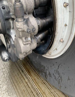
(fig.1) Picture of the damaged piston
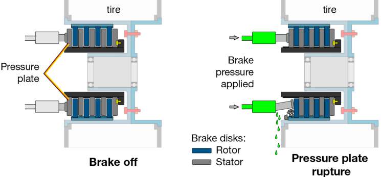
(fig.2) Rupture of the pressure plate during brake pressure application with damage to one of the brake pistons.
BRAKE WEAR VS. BRAKE OXIDATION
Section titled “BRAKE WEAR VS. BRAKE OXIDATION”Brakes are subject to two different phenomena: Wear and oxidation.
Brake wear
Section titled “Brake wear”Brake wear is the progressive loss of width on the brake disks due to friction. Brake wear on carbon brakes depends on the number of brake applications and on the brake temperature. Each carbon brake type has its own temperature range for optimum operation and its temperature range for maximum wear. The temperature range varies from one brake manufacturer to another.
Guaranteed braking efficiency until the wear limit
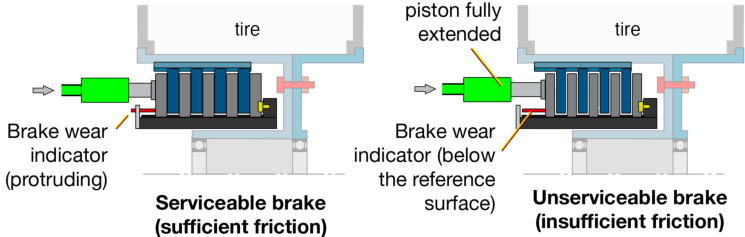
Section titled “Guaranteed braking efficiency until the wear limit”Brakes are guaranteed to provide sufficient braking until the brake wear indicator is flushed with the reference surface. If the indicator is below the reference surface, the brake disks are too worn, and the braking performance can be significantly reduced. If the brake disks are too worn, their width is reduced. As a result, the pistons do not
have enough extension to push the disks and create sufficient braking friction to slow down the aircraft (fig.3). In addition, if the brake is too worn, the amount of heat sink mass that is available to absorb braking energy is reduced. In the event of a high speed RTO this can lead to increased risk of runway overrun or brake fire.
Brake oxidation
Section titled “Brake oxidation”Carbon from the brakes naturally combines with oxygen from the ambient air to become carbon dioxide (CO2). Under normal circumstances the oxidation occurs at a very slow rate. However the rate of oxidation can be accelerated by external factors such as high temperature and catalytic (chemical) pollution (table 1). This results in a loss of carbon mass from the brake disks, carbon softening, and delamination. It can ultimately lead to brake rupture if an affected brake is not changed in due time (fig.4). Carbon oxidation due to exposure to high temperatures is referred to as thermal oxidation. When carbon oxidation is due to the presence of catalysts, it is usually referred to as catalytic oxidation.
Thermal oxidation
Section titled “Thermal oxidation”Thermal oxidation is the main cause of accelerated degradation of carbon brakes. It can occur if high brake temperatures are reached after landing and during taxi. Thermal oxidation affects all brake disks, but the middle disks are most affected because they reach a higher temperature and take longer to cool down. Worn brakes tend to reach higher temperatures making them more prone to the effects of thermal oxidation.
(fig.3) Loss of braking performance due to brake wear
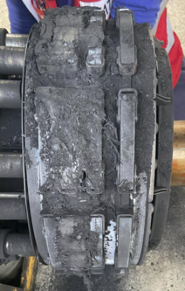
(fig.4) Heavily oxidized brake disks
Catalytic oxidation
Section titled “Catalytic oxidation”Catalytic oxidation of the brakes is generally caused by contact with deicing or cleaning fluids. The potassium or sodium coming from some aircraft and runway deicing fluids acts as a catalyst and further accelerates the oxidation (table 1). The presence of the catalyst also reduces the temperature at which significant oxidation occurs. When the potassium or sodium is absorbed by the carbon it remains within the material causing catalytic oxidation to continue well after the end of the winter season. The outer disks, including the pressure plate, are most exposed to external pollution and are usually more susceptible to catalytic oxidation.
| Time to lose 5 % mass | = Time to lose 25 % strength | |
|---|---|---|
| Temperature | ||
| Thermal oxidation only | Thermal + catalytic oxidation | |
| 25 °C | 7.5 x 10⁸ years | 3.6 x 10⁸ years |
| 400 °C | 3 years | 33 days |
| 500 °C | 14 days | 15 hours |
| 600 °C | 12 hours | 45 minutes |
| 700 °C | 49 minutes | 4 minutes |
(table 1) High temperatures and catalytic pollution significantly increase the oxidation rate of the brake carbon disks
Risks of brake rupture: loss of performance and potential brake fire
Section titled “Risks of brake rupture: loss of performance and potential brake fire”In addition to high maintenance costs, brake oxidation can lead to brake rupture and a loss of braking for the affected wheel. If maximum braking is necessary, such as in the case of a rejected takeoff at or close to the maximum takeoff weight, it may result in a runway overrun.
Brake rupture can also damage brake pistons and lead to leakage of hydraulic fluid. The fluid may vaporize and create smoke if it comes into contact with hot components. This could result in fire. The hydraulic fuses will limit the amount of hydraulic fluid lost and the fire should remain contained to the brake, but damage may be caused to nearby components. Maintenance personnel and flight crews both have a role to play to prevent brake rupture.
BRAKE MAINTENANCE
Section titled “BRAKE MAINTENANCE”There are a number of ways to identify worn brakes and prevent brake rupture including visual checks, inspection, and taking precautions when using deicing or cleaning fluids.
Regularly check the brake wear indicator
Section titled “Regularly check the brake wear indicator”The Maintenance Planning Document (MPD) requires a regular visual inspection of the brake wear indicator to assess the level of thickness loss of the brake disks (table 2). The check must be done with the braking applied (parking brake ON or pedal pressed or BITE activated). If the brake wear indicator is flushed with the reference surface, the brake unit must be changed.
| A300/A310 | A320 family | A330/A340 | A350 | A380 |
|---|
(table 2) MPD interval for checking the brake wear indicator
A220 brake wear monitoring
Section titled “A220 brake wear monitoring”Brake wear monitoring is done via the EICAS STATUS synoptic page (fig.5). This page provides an indication of the status of the brake wear. When brakes are 100 % worn, three amber bars appear on the EICAS STATUS and a L_BRAKE FAIL or R_BRAKE FAIL caution message appears if the parking brake is applied. If this indication becomes inoperative, the MMEL requests a daily check of the mechanical brake wear indicator located on the brake assembly.
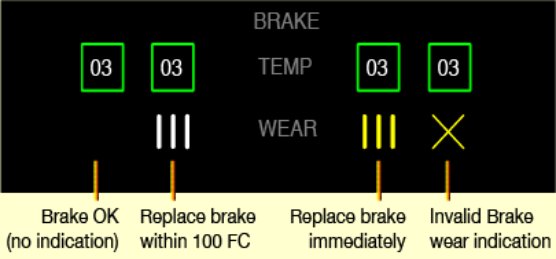
(fig.5) Brake information on the A220 EICAS STATUS synoptic page
To estimate the remaining service time of a brake unit, an average wear rate of 1 mm (0.04 in.) for every 20 flight cycles can be used. This number of flight cycles is an average value and can be customized depending on the aircraft operations and aircraft type.
Inspect the brake
Section titled “Inspect the brake”Visually inspect the brake assembly at every wheel removal, in accordance with the corresponding AMM/MP procedure, to check that there is no damage or crack on the disks and to check the condition of the brake components. Pay particular attention to any signs of oxidation marks, and if the oxidation is beyond acceptable limits, replace the brake (fig.6).
Brake manufacturers provide training for maintenance personnel to better detect brake disk oxidation. Operators can contact their brake manufacturer for more information.
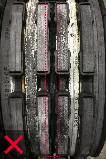
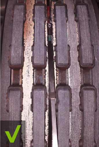
No sign of oxidation Oxidized stator 3
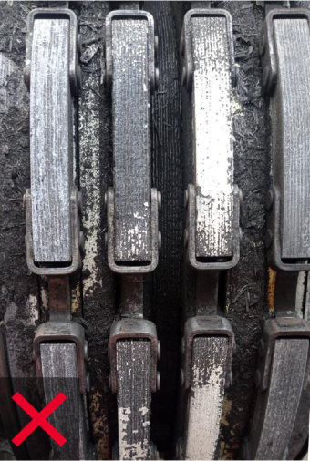
Highly oxidized brake
(fig.6) Examples of non-oxidized and oxidized brakes
Optional AMM inspection for A320 aircraft
Section titled “Optional AMM inspection for A320 aircraft”Some operators are more exposed to the risk of brake rupture due to their specific operations. Airbus proposes an optional brake inspection with the wheel removed. This inspection was developed together with brake manufacturers and can be added to the AMM procedure by request of the operator. Steps were added to the brake inspection procedure that require measuring the outer perimeter of the central stator (Safran Landing Systems and Messier-Goodrich brakes) (fig.7) or the radius of the friction surface (Collins Aerospace brakes) (fig.8). The reduction of this measured value provides an additional indicator of brake oxidation.
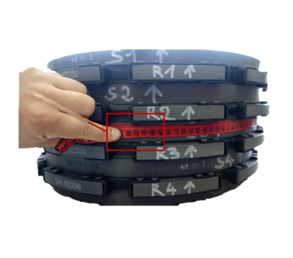
(fig.7) Optional inspection to measure the perimeter of the central stator on Safran Landing Systems and Messier-Goodrich brakes
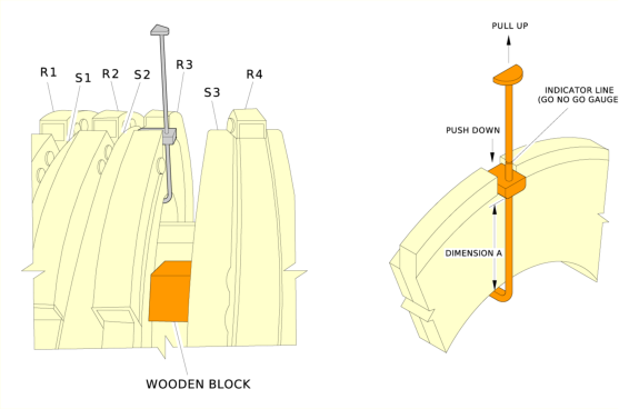
(fig.8) Optional inspection to the radius of the friction surface on Collins brakes
Report any brake damage/rupture
Section titled “Report any brake damage/rupture”Airbus encourages operators to report any brake damage or rupture through the Tech Request tool using the Brake Disk Failure Reporting Sheet available in the AMM/MP procedure for brake inspection.
Precautions during Cleaning and Deicing
Section titled “Precautions during Cleaning and Deicing”When cleaning the aircraft or performing deicing, particular care should be taken to prevent fluids coming into contact with the wheels and brakes. Always follow the AMM/MP/AMP procedures for cleaning and deicing and protect wheels and brakes to prevent them from becoming contaminated with chemicals that will accelerate oxidation.
OPERATIONAL CONSIDERATIONS
Section titled “OPERATIONAL CONSIDERATIONS”The flight crew can detect worn brakes before the flight during the exterior walkaround. They can reduce wear and oxidation by using the brakes in an optimal manner during taxi and landing.
Brake wear indicator check on walkaround
Section titled “Brake wear indicator check on walkaround”A quick check of the brake wear indicator (fig.9) during the exterior walkaround will determine if the brakes are worn. If there are only a few millimeters remaining before the indicator is flush with the reference plate, inform maintenance personnel to anticipate and plan for a brake replacement before the wear limit is reached. On A220 aircraft, the flight crew can also check the brake wear status on the EICAS STATUS synoptic page.
Reducing brake use during taxi
Section titled “Reducing brake use during taxi”Flight crews should reduce the number of brake applications during taxi to limit brake wear. The FCTM and A220 FCOM recommend that on long, straight taxiways, and with no ATC or other ground traffic constraints, the PF should allow the aircraft to accelerate to 30 kt of ground speed, and then use one smooth brake application to decelerate to 10 kt.
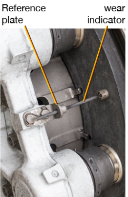
(fig.9) Brake wear indicator of an A350-1000 aircraft
Keep thrust at idle
Section titled “Keep thrust at idle”Maintaining idle thrust during taxi enables a reduced number of brake applications to keep the aircraft below the 30 kt maximum taxi speed.
Single engine taxi
Section titled “Single engine taxi”Single engine taxi is a fuel saving initiative that also reduces brake wear, because it further reduces the idle thrust during taxi.
Reducing braking energy at landing
Section titled “Reducing braking energy at landing”The number of thermal oxidation reports is increasing, especially on the A320 family fleet. This phenomenon may be linked with efforts by many operators to save fuel. It was observed that a majority of operators reporting high thermal oxidation were using CONF 3 and thrust reversers on IDLE at landing. There is a trade-off between fuel savings, engine maintenance costs, and increased brake replacement due to higher rates of oxidation. This will depend on the flight conditions, aircraft condition, and the operator’s policy.
Use of Flaps FULL (or FLAP 5 on A220)
Section titled “Use of Flaps FULL (or FLAP 5 on A220)”The use of flaps FULL (FLAP 5 on A220) at landing reduces the approach speed, and therefore, the aircraft energy to be absorbed by the brakes.
Use of autobrake or Brake-to-vacate (BTV) at landing
Section titled “Use of autobrake or Brake-to-vacate (BTV) at landing”Use of autobrake or BTV (if installed) enables a single brake application with an optimized braking intensity. When autobrake is used and if conditions permit, the use of autobrake LOW reduces the heat of the brakes, and therefore, reduces the likelihood of oxidation.
Updated AUTOBRAKE LOW mode for A320 family aircraft
Section titled “Updated AUTOBRAKE LOW mode for A320 family aircraft”An updated autobrake LOW mode with a slightly increased deceleration rate (2 m/s[2] instead of 1.7 m/s[2] ) and a shorter delay for brake application (2 s instead of 4 s) was introduced on recent A320 aircraft. This updated LOW mode enables the use of the LOW mode on shorter runways and reduces the observed tendency of the flight crew to switch to manual braking due to a perception of late and low braking application. This updated autobrake mode is installed on A320 family aircraft delivered since Q2 2018 and can be retrofitted on earlier aircraft using a dedicated Service Bulletin (SB) (table 3).
|---|---|---|---|---| |SB 32-1464|SB 32-1465|SB 32-1476|SB 32-1477||
Timely thrust reduction during flare
Section titled “Timely thrust reduction during flare”A timely thrust reduction during the landing flare prevents extra thrust provided by the autothrust trying to maintain Vapp after the flare. The flight crew should retard the thrust levers at 20 ft (A320/A330/A340/A350/A380) or 30 ft (A220/A300/A310) as per the SOP, and at the latest, at landing gear touchdown to enable spoiler extension.
Use of thrust reversers at landing
Section titled “Use of thrust reversers at landing”The use of thrust reversers reduces the energy to be absorbed by the brakes. It is therefore a good option to use thrust reversers to limit brake oxidation, especially on short runways.
Use most appropriate runway exit
Section titled “Use most appropriate runway exit”Taking over the autobrake to use full or strong manual braking to quickly slow down the aircraft in order to reach a specific runway exit may save some taxi time. However, this will also significantly increase brake wear. Using the next exit may slightly increase taxi time, but will also reduce brake wear and temperature.
Use of brake fans
Section titled “Use of brake fans”The use of brake cooling fans, when available, reduces the exposure time of the brake units to high temperature after landing. This reduces the effects of carbon thermal oxidation.
Contributors:
Fabien ARNE Braking & Steering System Engineer Customer Support
Bertrand PLANTE Brake Engineering Specialist Principal A220 Design Office
Andy SAMUELS Braking Specialist Design Office
Alexandre SAVOUREY Training & Flight Ops Pilot Instructor Flight Operations Support
With thanks to Jimmy AVGOUSTIS from the A220 Flight Operations support, Frederic BOUCHER and Simon CAMERON from the Design Office and Laurent COUTURET from Customer Support.
Maximum available braking performance is necessary to prevent the risk of a runway overrun in an event such as a rejected takeoff with a fully loaded aircraft. Brakes need to be closely monitored to ensure that they do not have excessive wear or oxidation that will affect the braking performance of the aircraft or to ensure that they do not degrade to a condition that could cause a brake rupture.
The flight crew or maintenance personnel can quickly check brake wear during the exterior walkaround inspection by looking at the brake wear indicator pin on each brake unit. If the indicator is flush with the reference plate, or below it, the brake must be changed.
It is important to perform a careful visual inspection of the brake assembly at every wheel removal to check for signs of excessive oxidation. Operators should consider adding the optional inspection check developed with the brake manufacturers into their AMM/MP.
Flight crews can apply a number of recommended procedures and techniques to help reduce the rates of brake wear and oxidation. This includes reducing the number of brake applications during taxi, applying techniques that will reduce braking energy at landing, and using brake fans when available. These operational and maintenance considerations will ensure that the brakes have a longer service life and are in a condition to create the necessary friction for optimal aircraft braking performance.
Safety first, 2022. Safety first is published by Airbus S.A.S. 1, rond point Maurice Bellonte - 31707 Blagnac Cedex/France.
Editor: Yannick Malinge, Chief Product Safety Officer.
Editorial team: Guillaume Estragnat, Vanessa Sadi, Gwyneth Duggan, Tim Roach.
Photos by Airbus.
善待您的刹车
Section titled “善待您的刹车”来源:Airbus Safety First 网址:https://safetyfirst.airbus.com/take-care-of-your-brakes/ 发布日期:2022-09-15 类别:飞行运营、维护、自动刹车、刹车、减速脱离刹车、减速脱离速度
所有刹车都会受到磨损。部分刹车还可能发生氧化,这可能导致刹车破裂。一旦发生刹车破裂或刹车磨损过度,飞机的制动能力会下降。如果需要最大制动能力(例如在接近最大起飞重量的中断起飞情况下),这可能导致制动性能不足而冲出跑道。刹车破裂还可能导致损坏,进而引发刹车起火,因为液压油会与高温部件接触。
本文阐述了碳磨损和氧化现象,回顾了用于识别磨损或氧化刹车的维护程序、飞行机组程序,以及防止刹车磨损和氧化的良好实践。
本文也可在 safetyfrst.airbus.com 以及 iOS 和 Android 设备上的 Safety First 应用中获取。
一架 A330 飞机着陆后滑行进入过程中,飞行机组听到了一声强烈而异常的噪音。当飞机到达停机位时,地面人员观察到左主起落架 (MLG) 区域冒烟,并通知了飞行机组。消防队赶到后未发现明火。飞行机组发现 6 号轮的温度达到 400 °C。维修人员对起落架进行了快速检查,发现 6 号轮的一个刹车活塞扭曲并从外壳中脱落,液压油泄漏痕迹明显**(图 1)**。起落架结构和部件上没有起火痕迹。
调查表明,最可能的原因是刹车压力板在刹车施加过程中发生破裂。刹车活塞冲破压力板并接触到第一个转子**(图 2)**。这给活塞施加了一个侧向力,导致其从外壳中脱落并造成液压油泄漏。泄漏到刹车高温部件上的液压油产生了烟雾。经检查发现,压力板已严重氧化,这就是刹车活塞压向压力板时导致其破裂的原因。
(图 1) 受损活塞的照片
(图 2) 刹车加压期间压力板破裂,活塞受损。
刹车磨损与刹车氧化
Section titled “刹车磨损与刹车氧化”刹车面临两种不同的现象:磨损和氧化。
刹车磨损是刹车盘因摩擦而逐渐变薄的过程。碳刹车的磨损取决于刹车使用次数和刹车温度。每种碳刹车都有其最佳工作温度范围和最大磨损温度范围。温度范围因刹车制造商而异。
磨损极限内保证制动效率
Section titled “磨损极限内保证制动效率”在刹车磨损指示器与参考表面平齐之前,刹车保证提供足够的制动力。如果指示器低于参考表面,则说明刹车盘磨损过度,制动性能可能会显著降低。如果刹车盘磨损过度,其宽度会减小。结果是活塞没有足够的行程来推动刹车盘并产生足够的制动力来减速飞机**(图 3)**。此外,如果刹车磨损过度,可用热沉质量会减少,从而吸收制动能量的能力降低。在高速中断起飞的情况下,这可能导致冲出跑道的风险增加或刹车起火。
刹车中的碳会自然与周围空气中的氧结合生成二氧化碳 (CO2)。在正常情况下,氧化过程非常缓慢。然而,外部因素(如高温和催化(化学)污染)会加速氧化速率**(表 1)。这会导致刹车盘碳质量损失、碳软化和脱层。如果受影响刹车未及时更换,最终可能导致刹车破裂(图 4)**。因高温暴露而导致的碳氧化称为热氧化。当碳氧化是由催化剂存在引起时,通常称为催化氧化。
热氧化是碳刹车加速降解的主要原因。它可能在着陆后和滑行期间达到高刹车温度时发生。热氧化会影响所有刹车盘,但中间刹车盘受影响最大,因为它们达到的温度更高且冷却时间更长。磨损的刹车更容易达到更高温度,使其更容易受到热氧化的影响。
(图 3) 刹车磨损导致的制动性能损失
(图 4) 严重氧化的刹车盘
刹车的催化氧化通常由与除冰液或清洁液接触引起。来自某些飞机和跑道除冰液的钾或钠充当催化剂,进一步加速氧化过程 (表 1)。催化剂的存在也会降低发生显著氧化的温度。当钾或钠被碳吸收后,会残留在材料内,导致催化氧化在冬季结束很长一段时间后仍在持续。外侧制动盘,包括压力板,最容易受到外部污染的影响,通常更容易发生催化氧化。
| 损失 5% 质量所需时间 | = 损失 25% 强度所需时间 | |
|---|---|---|
| 温度 | ||
| 仅热氧化 | 热氧化 + 催化氧化 | |
| 25 °C | 7.5 x 10⁸ 年 | 3.6 x 10⁸ 年 |
| 400 °C | 3 年 | 33 天 |
| 500 °C | 14 天 | 15 小时 |
| 600 °C | 12 小时 | 45 分钟 |
| 700 °C | 49 分钟 | 4 分钟 |
(表 1) 高温和催化污染会显著加快刹车碳制动盘的氧化速度
刹车断裂的风险:性能丧失和潜在的刹车起火
Section titled “刹车断裂的风险:性能丧失和潜在的刹车起火”除了高昂的维护成本外,刹车氧化还可能导致刹车断裂和相关机轮制动能力的丧失。如果需要最大制动,例如在最大起飞重量或接近最大起飞重量时中断起飞,可能导致冲出跑道。
刹车断裂还可能损坏刹车活塞并导致液压油泄漏。液压油接触高温部件时可能汽化并产生烟雾,由此可能引发火灾。液压保险将限制液压油的流失量,火灾应被限制在刹车范围内,但可能会对附近部件造成损坏。维护人员和飞行机组都有责任防止刹车断裂。
有多种方法可以识别磨损的刹车并防止刹车断裂,包括目视检查、详细检查以及使用除冰液或清洁液时采取预防措施。
定期检查刹车磨损指示器
Section titled “定期检查刹车磨损指示器”维护计划文件(MPD)要求定期目视检查刹车磨损指示器,以评估刹车盘厚度损失程度 (表 2)。检查必须在施加制动时进行(驻车刹车接通或踩下脚蹬或启动 BITE)。如果刹车磨损指示器与参考面平齐,则必须更换刹车组件。
| A300/A310 | A320 系列 | A330/A340 | A350 | A380 |
|---|
(表 2) 检查刹车磨损指示器的 MPD 间隔
A220 刹车磨损监控
Section titled “A220 刹车磨损监控”刹车磨损监控通过 EICAS STATUS 页面进行 (图 5)。此页面提供刹车磨损状态指示。当刹车 100% 磨损时,EICAS STATUS 上会出现三条琥珀色条带,如果应用了驻车刹车,则会显示 L_BRAKE FAIL 或 R_BRAKE FAIL 注意信息。如果此指示失效,最低设备清单(MMEL)要求每日检查安装在刹车组件上的机械刹车磨损指示器。
(图 5) A220 EICAS STATUS 页面的刹车信息
为估算刹车组件的剩余使用时间,可使用每 20 个飞行循环平均磨损 1 mm(0.04 英寸)的磨损率。这一飞行循环数是一个平均值,可根据飞机运营情况和飞机类型进行定制。
每次拆卸机轮时,应按照相应的 AMM/MP 程序对刹车组件进行目视检查,检查制动盘是否有损坏或裂纹,并检查刹车组件的状况。特别注意任何氧化痕迹的迹象,如果氧化超出可接受范围,则更换刹车 (图 6)。
刹车制造商为维护人员提供培训,以便更好地检测刹车盘氧化情况。运营商可联系其刹车制造商了解更多详情。
无氧化痕迹 定子 3 氧化
严重氧化的刹车
(图 6) 未氧化和已氧化刹车的示例
A320 飞机的可选 AMM 检查
Section titled “A320 飞机的可选 AMM 检查”某些运营商由于其特定运营活动而面临更高的刹车断裂风险。空客提议在拆下机轮后进行可选的刹车检查。此检查与刹车制造商共同开发,可应运营商要求添加到 AMM 程序中。检查步骤中增加了测量中央定子外周长(Safran Landing Systems 和 Messier-Goodrich 刹车)(图 7) 或摩擦面半径(Collins Aerospace 刹车)(图 8) 的要求。该测量值的减小可作为刹车氧化的额外指示。
(图 7) Safran Landing Systems 和 Messier-Goodrich 刹车中央定子周长的可选检查
(图 8) Collins 刹车摩擦面半径的可选检查
报告任何刹车损坏/破裂情况
Section titled “报告任何刹车损坏/破裂情况”空客鼓励运营商通过 Tech Request 工具报告任何刹车损坏或破裂情况,使用 刹车盘故障报告表,该表格可在 AMM/MP 刹车检查程序中获取。
清洁和除冰期间的注意事项
Section titled “清洁和除冰期间的注意事项”清洁飞机或进行除冰时,应特别注意防止液体接触轮子和刹车。在清洁和除冰时应始终遵循 AMM/MP/AMP 程序,并保护轮子和刹车,防止其被化学物质污染,从而加速氧化。
运营注意事项
Section titled “运营注意事项”飞行机组可以在飞行前的外部绕机检查期间检测到刹车磨损情况。他们可以通过在滑行和着陆期间以最佳方式使用刹车来减少磨损和氧化。
绕机检查时检查刹车磨损指示器
Section titled “绕机检查时检查刹车磨损指示器”在外部绕机检查期间快速检查刹车磨损指示器 (图 9) 可确定刹车是否磨损。如果指示器与参考板平齐前仅剩几毫米,应通知维修人员,以便在达到磨损极限前预计并计划更换刹车。在 A220 飞机上,飞行机组还可以通过 EICAS STATUS 状态页面查看刹车磨损状态。
减少滑行期间的刹车使用
Section titled “减少滑行期间的刹车使用”飞行机组应减少滑行期间的刹车使用次数,以限制刹车磨损。FCTM 和 A220 FCOM 建议,在长直滑行道上,且没有 ATC 或其他地面交通限制的情况下,PF 应让飞机加速至地速 30 kt,然后使用一次平稳的刹车使速度减速至 10 kt。
(图 9) A350-1000 飞机刹车磨损指示器
保持慢车推力
Section titled “保持慢车推力”在滑行期间保持慢车推力可减少刹车使用次数,使飞机保持在 30 kt 最大滑行速度以下。
单发滑行是一项节省燃油的措施,同时也能减少刹车磨损,因为它进一步降低了滑行期间的慢车推力。
减少着陆时的刹车能量
Section titled “减少着陆时的刹车能量”热氧化报告的数量正在增加,尤其是在 A320 系列机队中。这一现象可能与许多运营商努力节约燃油有关。据观察,报告高热氧化的运营商大多数在着陆时使用 CONF 3 且反推处于慢车状态。燃油节省、发动机维护成本与因更高氧化率导致的刹车更换增加之间存在权衡。这将取决于飞行条件、飞机状况和运营商的政策。
使用全形态(缝翼)(或 A220 上的 FLAP 5)
Section titled “使用全形态(缝翼)(或 A220 上的 FLAP 5)”着陆时使用全形态(缝翼)(A220 上为 FLAP 5)可降低进近速度,从而降低飞机需要由刹车吸收的能量。
着陆时使用自动刹车或 BTV(刹车至脱离)
Section titled “着陆时使用自动刹车或 BTV(刹车至脱离)”使用自动刹车或 BTV(如已安装)可实现单次刹车应用,且刹车强度经过优化。当使用自动刹车且条件允许时,使用自动刹车 LOW 可降低刹车热量,从而减少氧化的可能性。
A320 系列飞机自动刹车 LOW 模式更新
Section titled “A320 系列飞机自动刹车 LOW 模式更新”更新后的自动刹车 LOW 模式具有略微增加的减速率(2 m/s² 而非 1.7 m/s²)和更短的刹车应用延迟(2 秒而非 4 秒),已在最新的 A320 飞机上引入。此更新后的 LOW 模式使 LOW 模式可在更短的跑道上使用,并减少了飞行机组因感知到刹车应用延迟且力度不足而切换至人工刹车的倾向。此更新的自动刹车模式已安装在自 2018 年第二季度以来交付的 A320 系列飞机上,并可通过专用服务通告(SB)改装至早期飞机 (表 3)。
|---|---|---|---|---|---| |SB 32-1464|SB 32-1465|SB 32-1476|SB 32-1477||
拉平阶段及时减推力
Section titled “拉平阶段及时减推力”拉平阶段及时减推力可防止自动推力在拉平后试图维持 Vapp 时产生的额外推力。按照 SOP,机组应在 20 ft(A320/A330/A340/A350/A380)或 30 ft(A220/A300/A310)收回推力手柄,最迟应在起落架接地时,以使扰流板展开。
着陆时反推的使用
Section titled “着陆时反推的使用”使用反推可减少刹车需要吸收的能量。因此,使用反推是限制刹车氧化的良好选择,尤其是在短跑道上。
使用最合适的跑道出口
Section titled “使用最合适的跑道出口”接管自动刹车以使用全强度或强刹车快速减速飞机,从而到达指定的跑道出口,可能会节省一些滑行时间。然而,这也会显著增加刹车磨损。使用下一个出口可能会略微增加滑行时间,但也会减少刹车磨损和温度。
刹车风扇的使用
Section titled “刹车风扇的使用”在有条件时使用刹车冷却风扇,可降低着陆后刹车组件暴露于高温的时间。这可减少碳热氧化的影响。
贡献者:
Fabien ARNE 制动与转向系统工程师 客户支援
Bertrand PLANTE 刹车工程专家 A220 设计办公室首席工程师
Andy SAMUELS 制动专家 设计办公室
Alexandre SAVOUREY 培训与飞行运营飞行员教官 飞行运营支援
感谢 A220 飞行运营支援团队的 Jimmy AVGOUSTIS、设计办公室的 Frederic BOUCHER 和 Simon CAMERON,以及客户支援团队的 Laurent COUTURET 的贡献。
在诸如满载飞机中断起飞等情况下,防止跑道冲出所需的最高可用制动性能至关重要。必须密切监控刹车,确保其没有过度磨损或氧化,以免影响飞机的制动性能,或确保其状态不会退化到可能导致刹车破裂的程度。
机组或维护人员可在外部绕机检查期间通过查看每个刹车组件上的刹车磨损指示销快速检查刹车磨损。如果指示销与参考板平齐或低于参考板,则必须更换刹车。
每次拆下轮胎时,对刹车组件进行仔细的目视检查以检查是否有过度氧化的迹象非常重要。运营人应考虑将,与刹车制造商共同开发的可选检查项目添加到其 AMM/MP 中。
机组可采用多项建议的程序和技术来帮助降低刹车磨损和氧化的速率。这包括减少滑行期间的刹车使用次数、应用可降低着陆制动能量的技术,以及在有条件时使用刹车风扇。这些运营和维护方面的考虑将确保刹车具有更长的使用寿命,并处于能够产生必要摩擦力以实现最佳飞机制动性能的状态。
Safety first, 2022. Safety first 由空中客车公司出版。1, rond point Maurice Bellonte - 31707 Blagnac Cedex/France。
编辑:Yannick Malinge,产品安全总监。
编辑团队:Guillaume Estragnat、Vanessa Sadi、Gwyneth Duggan、Tim Roach。
照片由空中客车公司提供。