Control your speed… at take-off
Source: Airbus Safety First URL: https://safetyfirst.airbus.com/control-your-speed-at-take-off/ Published: 2014-07-29 Magazine Issue: 2014-07 Category: Flight Ops, characteristic, decision, energy, gw, performance, RTO, speed, SRS, take off, takeoff, TOGA, v1, v2, vef, vlof, vmbe, vmca, vmcg, vmu, Vr, vs1g, weight, zfw PDF: Original PDF
PROCEDURES
Section titled “PROCEDURES”Control your speed… at take-off

One of the most critical decisions that every line pilot may potentially encounter during every take-off is to continue or abort the procedure; hence the essential need to properly monitor the airspeed during this phase.


LORRAINE DE BAUDUS
Section titled “LORRAINE DE BAUDUS”A320/A330/A340 Flight Operations Safety Enhancement
PHILIPPE CASTAIGNS Experimental Test Pilot
Section titled “PHILIPPE CASTAIGNS Experimental Test Pilot”
Overlooking the airspeed during take-off or conducting a takeoff with an inappropriate speed are directly associated to the following main risks: a lateral or longitudinal runway excursion, maximum brake energy exceedance resulting in a brake fi re, tail strike, lack of lateral control once the aircraft is airborne, or obstacle clearance trespassing.
This article aims at providing some reminders on the ways the various take-off characteristic and limit speeds are elaborated from the certifi cation requirements to the fl ight test validation, and how they can be implemented in daily operations.
We will offer a series of articles on this topic, in the present and future issues of our magazine, aiming to detail everything you always wanted to know about speeds… but were afraid to ask. The lines that follow are focusing on the take-off phase.
SECURING YOUR TAKE-OFF: UNDERSTANDING SPEEDS
Section titled “SECURING YOUR TAKE-OFF: UNDERSTANDING SPEEDS”Characteristic speeds are intended to provide reference points that can be used by pilots as a guide in making judgement in a very dynamic situation. In this respect, they need close supervision. What speeds exactly should be monitored? What do these speeds mean and where do they come from? What happens if such speeds are exceeded?
Our objective is to highlight the design and operational considerations underlying all recommendations Airbus has issued to fl ight crews regarding speed monitoring during take-off.
craft take-off performance limits and the margins that exist in the event of a failure (fi g.1).
For every aircraft type, V1, VR and V2 are computed by Airbus on the basis of design speeds and evidence collected during the certifi cation testing of the airplane.
Take-off operating speeds V1, VR and V2 very precisely frame the air-
For every aircraft type, V1, VR and V2 are computed by Airbus on the basis of design speeds and evidence collected during the certifi cation testing of the airplane.
TAKE-OFF
Section titled “TAKE-OFF”(fi g.1)
Section titled “(fi g.1)”V1: Decision speed VR: Rotation speed V2: Take-off safety speed
V1 VR V2
PROCEDURES
Section titled “PROCEDURES”Control your speed… at take-off
V1: Decision speed
Section titled “V1: Decision speed”Definition
Section titled “Definition”V1 is the maximum speed at which a rejected take-off can be initiated in the event of an emergency.
V1 is also the minimum speed at which a pilot can continue take-off following an engine failure.
In addition, if an engine failure occurs after V1, then the aircraft must be able to achieve safely take-off with TOGA or derated power (enough lateral control).
These two conditions require identifying:
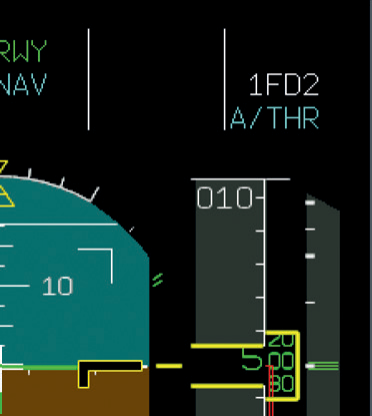
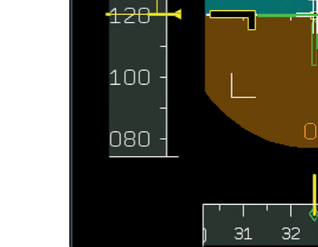
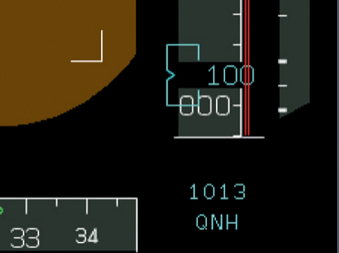
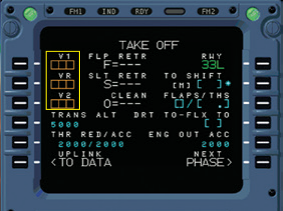
This speed is entered by the crew in the MCDU during fl ight preparation, and it is represented by a “1” on the speed scale of the PFD during takeoff acceleration (fi g.2).
How is V1 determined?
Section titled “How is V1 determined?”• The ground speed at which maximum energy is put into the brakes, when a RTO is performed at MTOW. This limit speed is defi ned during Airbus fl ight tests and is called VMBE = Maximum Brake Energy speed. V1 must be lower than VMBE.
If take-off is aborted at V1, the aircraft must be able to be stopped before the end of the runway, without exceeding the maximum energy the brakes can absorb.
• The minimum speed during takeoff roll at which the aircraft can still be controlled after a sudden failure of one engine (be it a two or four-engine airplane).
(fi g.2) V1 on the PFD speed scale
In such a case, and if the take-off is continued, only the rudder will be able to counteract the yaw moment that is generated by asymmetric engine(s) thrust. Therefore if a failure occurs before reaching this minimum speed, the take-off must be interrupted to maintain control of the aircraft. This limit speed is determined during Airbus flight tests and is called VMCG = Minimum Control speed on the Ground. VMCG mainly depends on engine(s) thrust and pressure altitude. V1 must be greater than VMCG.
-
The maximum aircraft speed at
-
which the most critical engine can fail
without compromising the safe completion of take-off after failure recognition. This design speed is called
VEF = Engine Failure speed.
Section titled “VEF = Engine Failure speed.”Considering that it is generally assumed humans have a reaction time to an unexpected event (such as a failure) of 1 second, V1 must be greater than VEF.
In addition, if an engine failure happens at VEF, then it must be possible to continue and achieve safely takeoff with TOGA power. This means that VEF must be greater than VMCG.
Supposedly, there are two different ways of “disrespecting” the V1 speed criteria:
1. The crew decides to continue take-off while an engine failure occurred before V1. Standard procedures encourage the crew to reject take-off if an engine fails before V1. If take-off is
continued despite this recommendation, then the aircraft can potentially exit the runway laterally, or be unable to take-off before the end of the runway.
BEST PRACTICE
Section titled “BEST PRACTICE”In the event of an engine failure at low speed, any delay in reducing the thrust of the good engine(s) will lead to a loss of directional control and a very quick lateral deviation. Max rudder pedal and max manual differential braking may be required (refer to the new FCTM recommendation AO-020 “Low speed engine failure”).
2. An RTO is initiated above V1.
- Virtually, any take-off can be “successfully” rejected, on the proviso that the reject is initiated early enough and is conducted properly. In this respect, the crew must always be prepared to make a GO/ NO GO decision prior to the aircraft reaching V1.
Doing otherwise exposes the aircraft to an unsafe situation where there either may not be enough runway left to successfully stop the aircraft - therefore resulting in a longitudinal runway excursion-, or maximum brake energy is exceeded and brakes catch fire.
PROCEDURES
Section titled “PROCEDURES”Control your speed… at take-off
BEST PRACTICE
Section titled “BEST PRACTICE”As speed approaches V1, the successful completion of an RTO becomes increasingly more difficult. After V1, the crew must continue take-off and consider using TOGA thrust except if a derated take-off was performed (refer to FCOM PROABN-10 operating techniques).
V1 IN A NUTSHELL
Section titled “V1 IN A NUTSHELL”Do not continue take-off in the event of an engine failure below V1. Do not initiate an RTO at speeds in excess of V1.
VR: Rotation speed
Section titled “VR: Rotation speed”Definition
Section titled “Definition”VR is the speed at which rotation can be initiated at the appropriate rate of about 3° per second. VR ensures that V2 is reached at 35 feet above the runway surface at the latest, including in the event of an engine failure at VEF. Therefore at 35 feet, the actual speed is usually greater than V2.
still able to maintain lateral and directional control when the most adverse engine fails.
This limit speed is demonstrated by Airbus flight tests and is called VMCA = Minimum Control speed in the Air. VR shall not be lower than 1.04 or 1.05 VMCA, the factors 1.04 and 1.05 being defined by Airworthiness Authorities to ensure a safety margin.
How is VR determined?
Section titled “How is VR determined?”In principle, VR shall not be lower than V1.
In addition, whenever pilots initiate the rotation at VR, they must be assured that the aircraft will be controllable once airborne, including when the most adverse engine has failed after VEF.
On the upper end, if the rotation of the aircraft is started at VR at maximum practicable rate, lift-off must be possible at the end of the maneuver.
These concepts involve understanding the following limit speeds:
• The minimum speed in the second segment (take-off) at which the pilot is
• The minimum speed at which the aircraft becomes able to lift off and escape ground effect.
This limit speed is based on evidence collected during certification tests and is called VMU = Minimum Unstick speed. VMU is achieved by pitching the aircraft up to the maximum (tail on the runway, for aircraft that are geometrically limited) during the takeoff roll. The speed at which the aircraft first lifts off is VMU; therefore lift-off is not possible prior to VMU.
VMU is different from the design lift-off speed VLOF, which applies to general case scenarios and is necessarily greater than VMU, according to the following criteria:
The multiplicative factors that were applied were specified by Airworthiness Authorities, in consideration of safety margins.
1.04 or 1.05 VMU (N-1) VLOF 1.08 VMU (N) VLOF
PROCEDURES
Section titled “PROCEDURES”Control your speed… at take-off
In turn, VLOF is limited by the design speed VTIRE, which corresponds to the maximum tyre speed (tyre structural limit).
VLOF VTIRE
Section titled “VLOF VTIRE”Coming back to VR, if we consider that when a rotation is initiated at VR at the maximum practicable rate, it has to result in a satisfactory lift off speed, then VR must be limited by VLOF.
V1 VR 1.05 VMCA VR VR VLOF
What are the operational implications of not respecting VR?
Section titled “What are the operational implications of not respecting VR?”One direct consequence of initiating a rotation before VR is a tail strike. Second, if the rotation is done at VR but too slowly, or if the rotation is initiated after VR, then the aircraft intrinsic
performance will very likely not allow it to reach 35 feet at the end of the runway, and/or not respect the clearway if the take-off speeds were limited by the runway length or obstacles.
VR IN A NUTSHELL
Section titled “VR IN A NUTSHELL”Do not start rotation below or above VR.
V2: Take-off safety speed
Section titled “V2: Take-off safety speed”Defi nition
Section titled “Defi nition”V2 is the minimum take-off speed that the aircraft must attain by 35 feet above the runway surface with one engine failed at VEF, and maintain during the second segment of the take-off.
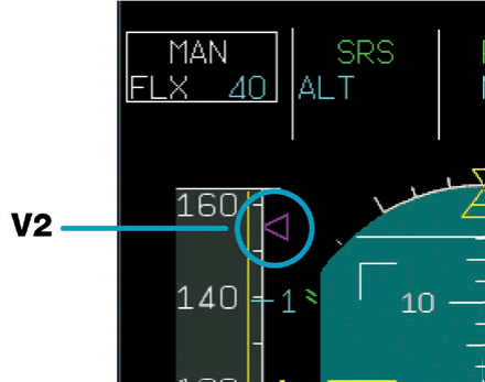
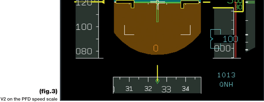
This speed must be entered by the crew during fl ight preparation, and is represented by a magenta triangle on the PFD speed scale (fi g.3).
V2 is always greater than VMCA and facilitates control of the aircraft in fl ight.
On the upper end, Airworthiness Authorities have agreed that all oper-
ating speeds must be referenced to a stall speed that can be demonstrated by fl ight tests. This speed is designated VS1g. V2 must obviously be greater than this stall speed.
1.13 VS1g V2 1.10 VMCA V2
The multiplicative factors that were applied were specifi ed by Airworthiness Authorities, in consideration of safety margins.
PROCEDURES
Section titled “PROCEDURES”Control your speed… at take-off
What are the operational implications of not respecting V2?
Section titled “What are the operational implications of not respecting V2?”Supposedly, there are two different ways of “disrespecting” the V2 speed criteria:
1. Flying below V2 in case of an engine failure.
The drag increase below V2 may lead to a situation where the only way to recover speed is to descend. If the speed further decreases and V2 is not recovered, then the high angle of attack protection may be reached, and the aircraft may ultimately enter into an unrecoverable descend trend. In particular, if the speed decreases below VMCA, the aircraft might not be recoverable due to lack of lateral control.
2. Flying above V2 in case of an engine failure.
Section titled “2. Flying above V2 in case of an engine failure.”In case of excessive speed, the required climb performance may not be reached, thus increasing the chance to trespass the obstacle clearance.
Take-off speeds in a nutshell
Section titled “Take-off speeds in a nutshell”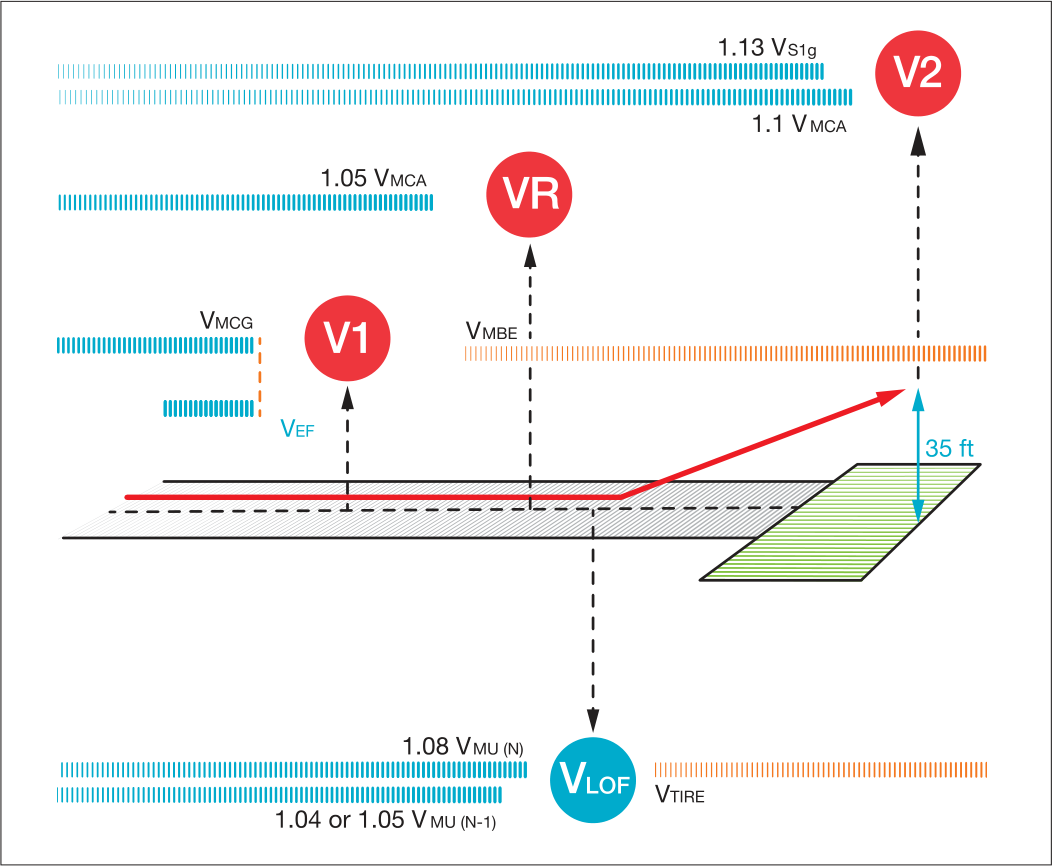
SECURING YOUR TAKE-OFF: THE ROLE OF THE PILOT MONITORING (PM)
Section titled “SECURING YOUR TAKE-OFF: THE ROLE OF THE PILOT MONITORING (PM)”The take-off phase is a very dynamic and demanding one, during which the PM plays a central role for a timely monitoring from cockpit preparation, all the way through take-off speeds computation and utilization.
Clearly flight crews are expected to be able to rapidly scan the essential and relevant parameters that support key decisions, such as continue or abort a take-off essentially. Doing so, the PM must be able to differentiate between situations that are detrimental to operational safety, and those that are not.
In this respect, he/she must be prepared to adapt his/her monitoring to the level of the threat and reach out in a communication sense to the PF to encourage action if necessary, by making callouts as per SOP. Callouts coupled to responses are a very effective means indeed to cope with demanding situations, and allow the crew to act as a well coordinated team.
Second, he/she must be aware of the primary threats to the safe completion of take-off in order to actively help to prevent take-off speed errors. Takeoff speed calculation errors are often due to a combination of two factors:
-
Error in parameter entry
-
Poor crosschecks by other crewmember.
Prevention strategies should therefore be developed to ensure efficient crosschecks, particularly after last-minute changes (runway change, loadsheet modification, etc).
For this purpose, we want to highlight the main factors often observed when analysing take-offs in which speeds were not respected:
Errors in take-off speed computation
Section titled “Errors in take-off speed computation”• Data issued from a computerized system is rarely challenged. However, incorrect inputs may occur, thus resulting in inadequate take-off speed values computation.
• In take-off speed calculations, Zero Fuel Weight (ZFW) is sometimes mistaken for Gross Weight (GW). This is particularly true when a last minute change occurs in cargo loading, or when time pressure and workload are high. Therefore calculated speeds
will be much lower than expected, and will potentially lead to tailstrikes, “heavy aircraft” sensation, and highspeed rejected take-offs.
• Take-off speeds calculations are based on specific configurations. Any change in the parameters of these configurations will invalidate take-off speeds. Examples of such parameters include a runway change, a wet runway that becomes contaminated, or a take-off from an intersection.
PROCEDURES
Section titled “PROCEDURES”Control your speed… at take-off
Errors in take-off speed utilization
Section titled “Errors in take-off speed utilization”• When a last minute change occurs, take-off speeds are sometimes modified and crosschecked during pushback or taxi. During such phases of flight, the PF workload is high. As a result, the PF may not have sufficient time or resources to perform efficient crosschecks.
-
If an incident occurs before V1, the
-
PM’s attention may be focused on
trying to assess the situation and may forget the V1 announcement.
• In the event of an engine failure after take-off, and in an attempt to climb faster, there may be a tendency to set a pitch attitude too high if FD bars are not followed. The aircraft is then flown below V2, and climb performance cannot be maintained.
OPERATIONAL RECOMMENDATIONS FOR THE PM
Section titled “OPERATIONAL RECOMMENDATIONS FOR THE PM”-
Compute/crosscheck V1, VR and V2.
-
Enter V1, VR and V2 in the FMS, and ensure these data are re-inserted during taxi as per SOP in case of last minute changes. Attention should be paid to keystroke errors.
-
Crosscheck information set or used by the PF.
-
Ensure a take-off briefing is conducted that highlights take-off speeds (particularly if they were changed during taxi), slats/ flaps configurations and weight.
-
For aircraft that are not equipped with a V1 auto-callout: pay a close attention to the V1 standard callout.
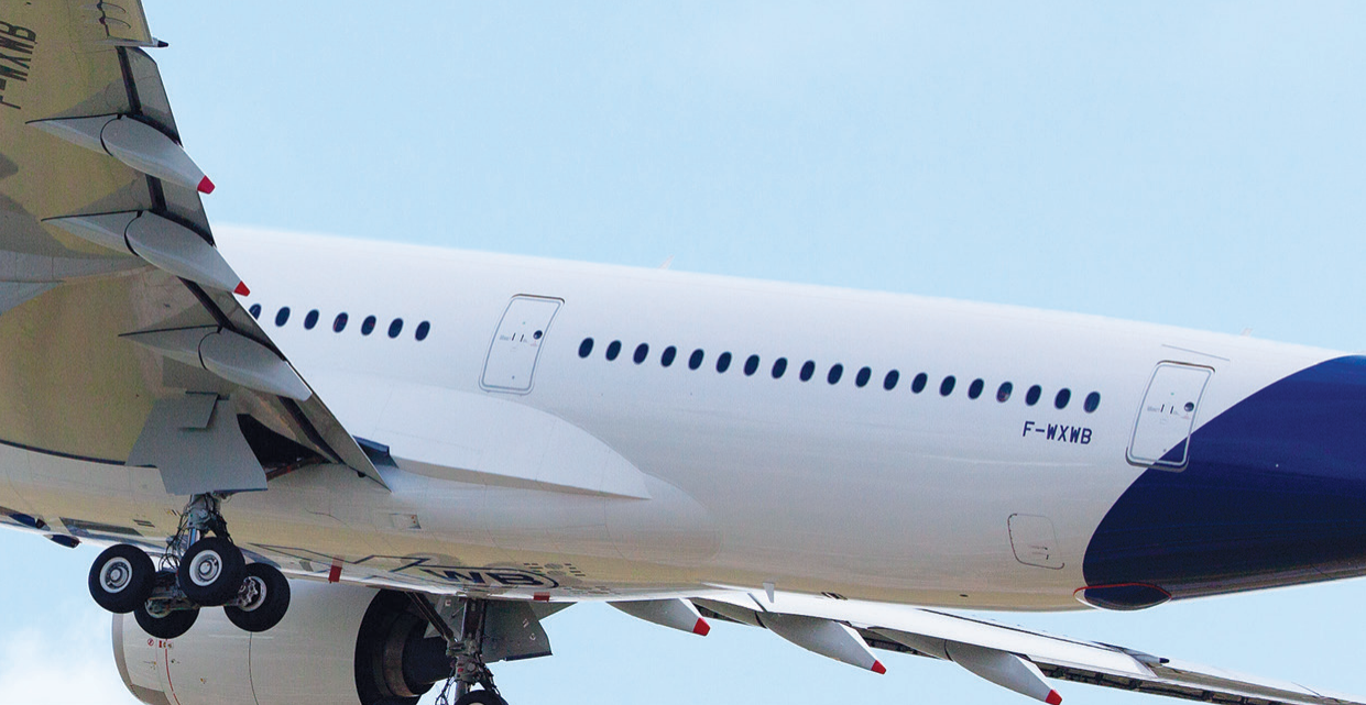

Understanding the implications of take-off speeds is paramount to enable pilots to sense instantly the available margin of maneuver they have left to preserve safety of flight, and make a wise GO/NO GO decision.
In practice, crew coordination and the PM’s involvement in the take-off phase preparation and execution are essential parameters to satisfactorily manage the risks associated to this particular phase of flight, such as: a lateral or longitudinal runway excursion, maximum brake energy exceedance causing a brake fire, tail strike, lack of lateral control once the aircraft is airborne, or obstacle clearance trespassing.
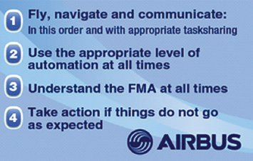
Whatever the flying conditions, it is essential that flight crews number one objective remains to fly the aircraft according to the 4 Golden Rules for Pilots.
DID YOU KNOW
Section titled “DID YOU KNOW”Read our brochure “Getting to grips with aircraft performance”, available on AirbusWorld.
控制您的速度…在起飞时
每次起飞时,每位航线飞行员都可能遇到的最关键决策之一是继续还是中止起飞程序;因此,在这一阶段正确监控空速至关重要。
LORRAINE DE BAUDUS
Section titled “LORRAINE DE BAUDUS”A320/A330/A340 飞行运营安全提升
PHILIPPE CASTAIGNS 试飞员
Section titled “PHILIPPE CASTAIGNS 试飞员”
起飞时忽略空速监控或以不适当的速度进行起飞,与以下主要风险直接相关:侧向或纵向跑道偏离、最大刹车能量超限导致刹车起火、尾撞、飞机离地后缺乏侧向控制,或障碍物净空违规。
本文旨在提供一些关于各类起飞特征速度和限制速度如何从认证要求制定到飞行试验验证,以及如何在日常运营中应用的提醒。
我们将在本期及后续杂志中推出关于此主题的一系列文章,旨在详细说明您一直想了解的速度相关知识…但又不敢问。以下内容将聚焦于起飞阶段。
确保起飞安全:理解速度
Section titled “确保起飞安全:理解速度”特征速度旨在提供参考点,供飞行员在高度动态的情况下作为判断的指导。因此,需要密切关注这些速度。究竟应监控哪些速度?这些速度的含义是什么?它们从何而来?如果超过这些速度会发生什么?
我们的目标是阐明空客向飞行机组发布的所有关于起飞期间速度监控建议背后的设计和运营考量。
飞机起飞性能限制及故障情况下的余量**(图1)**。
对于每种机型,V1、VR 和 V2 由空客根据设计速度和飞机认证测试期间收集的数据计算得出。
起飞操作速度 V1、VR 和 V2 精确地限定了空-
对于每种机型,V1、VR 和 V2 由空客根据设计速度和飞机认证测试期间收集的数据计算得出。
(图1)
V1:决策速度 VR:抬轮速度 V2:起飞安全速度
V1 VR V2
控制您的速度…在起飞时
V1:决策速度
Section titled “V1:决策速度”V1 是发生紧急情况时能够发起中断起飞的最大速度。
V1 也是发动机失效后飞行员能够继续起飞的最小速度。
此外,如果在 V1 之后发生发动机失效,飞机必须能够在使用 TOGA 或减推力的情况下安全完成起飞(足够的侧向控制)。
这两个条件要求确定:
此速度由机组在飞行准备时输入 MCDU,在起飞加速期间显示在 PFD 速度刻度上的”1”标记处**(图2)**。
V1 如何确定?
Section titled “V1 如何确定?”- 在以最大起飞重量执行中断起飞时,将最大能量输入刹车的地速。此限制速度由空客在飞行试验中确定,称为 VMBE = 最大刹车能量速度。V1 必须低于 VMBE。
如果在 V1 中断起飞,飞机必须能够在跑道尽头前停下,且不超过刹车能够吸收的最大能量。
- 在起飞滑跑期间,飞机在单台发动机突然失效后仍可控制的最小速度(无论是双发还是四发飞机)。
(图2) PFD 速度刻度上的 V1
在这种情况下,如果继续起飞,只有方向舵能够抵消由不对称发动机推力产生的偏航力矩。因此,如果在达到此最小速度之前发生失效,必须中断起飞以保持对飞机的控制。此限制速度由空客在飞行试验中确定,称为 VMCG = 地面最小控制速度。VMCG 主要取决于发动机推力和气压高度。V1 必须大于 VMCG。
- 最关键发动机失效时不会影响失效识别后安全完成起飞的最大飞机速度。此设计速度称为
VEF = 发动机失效速度
Section titled “VEF = 发动机失效速度”考虑到通常认为人类对突发事件(如失效)的反应时间为 1 秒,V1 必须大于 VEF。
此外,如果在 VEF 发生发动机失效,则必须能够继续安全起飞并达到 TOGA 推力。这意味着 VEF 必须大于 VMCG。
据推测,有两种不同的“违反”V1 速度标准的方式:
1. 机组在发动机失效发生在 V1 之前的情况下决定继续起飞。标准程序要求如果发动机在 V1 之前失效,机组应中断起飞。如果不顾建议继续起飞,则飞机可能会侧向冲出跑道,或无法在跑道尽头前起飞。
在发动机在低速失效的情况下,任何延迟减小正常发动机推力的行为都会导致方向控制丧失和非常快速的侧向偏移。可能需要最大方向舵踏板和最大手动差动刹车(请参阅新的 FCTM 建议 AO-020“低速发动机失效”)。
2. 在 V1 以上发起 RTO(中断起飞)。
- 实际上,任何起飞都可以“成功”中断,但前提是中断启动得足够早且执行正确。在这方面,机组必须在飞机到达 V1 之前始终做好准备做出继续/中断决策。
否则会使飞机处于不安全状态:要么可能没有足够的剩余跑道来成功停下飞机——因此导致纵向冲出跑道——要么超出最大刹车能量导致刹车起火。
起飞时的速度控制…
随着速度接近 V1,成功完成 RTO 变得越来越困难。在 V1 之后,机组必须继续起飞并考虑使用 TOGA 推力,除非进行了减功率起飞(请参阅 FCOM PROABN-10 操作技术)。
如果在 V1 以下发生发动机失效,不要继续起飞。如果速度超过 V1,不要发起 RTO。
VR:抬头速度
Section titled “VR:抬头速度”VR 是以适当速率(约每秒 3°)开始抬头的速度。VR 确保在最晚 35 英尺高度达到 V2,包括在 VEF 发生发动机失效的情况下。因此在 35 英尺高度,实际速度通常大于 V2。
在最具不利影响的发动机失效时,仍能保持横向和方向控制。
这一限制速度由空客飞行测试验证,称为 VMCA = 空中最小控制速度。 VR 不得低于 1.04 或 1.05 VMCA,系数 1.04 和 1.05 由适航当局定义以确保安全裕度。
VR 如何确定?
Section titled “VR 如何确定?”原则上,VR 不得低于 V1。
此外,每当飞行员在 VR 开始抬头时,必须确保飞机在起飞后可控,包括在最不利发动机已在 VEF 之后失效的情况下。
在上限方面,如果在 VR 以最大可行速率开始抬头,必须能够在动作结束时实现起飞。
这些概念涉及对以下限制速度的理解:
• 在第二阶段(起飞)中,飞行员能够
• 飞机能够起飞并脱离地面效应的最小速度。
这一限制速度基于认证测试期间收集的证据,称为 VMU = 最小离地速度。 VMU 是通过在起飞滑跑中将飞机抬头至最大角度(对于几何受限的飞机,尾翼接触跑道)来实现的。飞机首次离地的速度即为 VMU;因此在 VMU 之前不可能离地。
VMU 不同于设计离地速度 VLOF,后者适用于一般情况场景,根据以下标准必然大于 VMU:
所应用的乘数系数由适航当局规定,以考虑安全裕度。
1.04 或 1.05 VMU (N-1) VLOF 1.08 VMU (N) VLOF
起飞时的速度控制…
反过来,VLOF 受设计速度 VTIRE 限制,VTIRE 对应最大轮胎速度(轮胎结构限制)。
VLOF VTIRE
Section titled “VLOF VTIRE”回到 VR,如果我们考虑在 VR 以最大可行速率开始抬头,必须导致满意的离地速度,那么 VR 必须受 VLOF 限制。
V1 VR 1.05 VMCA VR VR VLOF
不遵守 VR 的操作影响是什么?
Section titled “不遵守 VR 的操作影响是什么?”在 VR 之前开始抬头的一个直接后果是尾翼擦地。其次,如果在 VR 但太慢地抬头,或者如果在 VR 之后开始抬头,那么飞机的固有性能很可能无法在跑道尽头达到 35 英尺,和/或如果起飞速度受跑道长度或障碍物限制,则无法遵守净空道要求。
不要在 VR 以下或以上开始抬头。
V2:起飞安全速度
Section titled “V2:起飞安全速度”V2 是飞机在起飞过程中,在跑道表面上方 35 英尺处、且在 VEF 时一发失效的情况下必须达到的最小起飞速度,并须在起飞的第二阶段保持该速度。
该速度须由机组在飞行准备阶段输入,并以品红色三角形显示在 PFD 速度刻度上**(图 3)。**
V2 始终大于 VMCA,便于飞机在空中进行控制。
在上限方面,适航当局已达成共识,所有运行速度均须参照可通过飞行试验验证的失速速度。该速度标注为 VS1g。V2 必须明显大于此失速速度。
1.13 VS1g V2 1.10 VMCA V2
所应用的倍数系数由适航当局规定,并考虑了安全裕度。
控制你的速度……在起飞阶段
不遵守 V2 会产生什么运行影响?
Section titled “不遵守 V2 会产生什么运行影响?”通常有两种不同的”违反”V2 速度标准的情况:
1. 发动机失效时低于 V2 飞行。
低于 V2 时的阻力增大可能导致这样一种情况:恢复速度的唯一方法是下降。如果速度进一步下降且未能恢复 V2,则可能触发高迎角保护,飞机最终可能进入不可改出的下降趋势。特别是当速度低于 VMCA 时,由于缺乏横侧向控制,飞机可能无法改出。
2. 发动机失效时高于 V2 飞行。
Section titled “2. 发动机失效时高于 V2 飞行。”若速度过高,可能无法达到所需的爬升性能,从而增加突破越障裕度的风险。
起飞速度概览
Section titled “起飞速度概览”
确 保 起 飞 安 全 :监 控 飞 行 员(PM)的角色
Section titled “确 保 起 飞 安 全 :监 控 飞 行 员(PM)的角色”起飞阶段是一个动态且要求极高 的阶段,在此期间 PM 从驾驶舱准备阶段到起飞速度的计算和使用,全程发挥着及时监控的核心作用。
显而易见,飞行机组须能够快速扫描关键决策所必需的相关参数,例如继续起飞还是中断起飞。在此过程中,PM 必须能够区分对运行安全有害的情况和无害的情况。
在这方面,PM 必须准备好根据威胁级别调整其监控方式,并在必要时通过沟通向 PF 发出提示以鼓励采取行动,依据 SOP 进行喊话。喊话与应答的配合确实是应对高要求情况的有效手段,能够使机组像一个协调良好的团队一样行动。
其次,PM 必须意识到安全完成起飞的主要威胁,以便积极帮助预防起飞速度错误。起飞速度计算错误通常由两个因素共同导致:
- 参数输入错误
- 其他机组成员交叉检查不力。
因此,应制定预防策略以确保高效的交叉检查,特别是在临时变更后(更换跑道、舱单修改等)。
为此,我们希望强调在分析未遵守速度的起飞事件时经常观察到的主要因素:
起飞速度计算错误
Section titled “起飞速度计算错误”• 计算机系统输出的数据很少受到质疑。然而,不正确的输入可能发生,从而导致计算出不当的起飞速度值。
• 在起飞速度计算中,零燃油重量(ZFW)有时会被误认为总重量(GW)。这种情况尤其容易发生在货物装载临时变更时,或时间压力和工作负荷较高时。因此计算出的速度将远低于预期,并可能导致尾蹭、“重飞机”感觉以及高速中断起飞。
• 起飞速度计算基于特定构型。任何这些构型参数的变更都将使起飞速度失效。这类参数的例子包括更换跑道、潮湿跑道变为污染跑道,或从交叉道口起飞。
控制你的速度……在起飞阶段
起飞速度使用错误
Section titled “起飞速度使用错误”• 当发生临时变更时,起飞速度有时会在推出或滑行期间进行修改和交叉检查。在这些飞行阶段,PF 的工作负荷很高。因此,PF 可能没有足够的时间或精力进行有效的交叉检查。
- 如果在 V1 之前发生事故,
- PM 的注意力可能集中在评
- 估情况上而忘记了 V1 喊话。
• 起飞后发生发动机失效时,为了更快爬升,可能会出现不跟随 FD 俯仰杆而设定过大俯仰姿态的趋势。飞机随后以低于 V2 的速度飞行,爬升性能无法维持。
给PM(监控飞行员)的操作建议
Section titled “给PM(监控飞行员)的操作建议”-
计算/交叉检查V1、VR和V2。
-
在FMS中输入V1、VR和V2,并按照SOP在滑行期间重新输入这些数据,以防最后时刻的变更。应注意按键输入错误。
-
交叉检查PF(操纵飞行员)设置或使用的信息。
-
确保进行起飞简令,其中突出起飞速度(特别是如果在滑行期间发生了变更)、缝翼/襟翼构型和重量。
-
对于未配备V1自动呼叫功能的飞机:应密切关注V1标准喊话。
理解起飞速度的含义至关重要,它能使飞行员立即感知剩余的可 用机动余量,从而保持飞行安全,并做出明智的继续起飞/中断起飞决策。
在实践中,机组配合以及PM在起飞阶段准备和执行过程中的参与,是有效管理这一特定飞行阶段相关风险的关键要素,例如:侧向或纵向跑道偏出、超过最大刹车能量导致刹车起火、尾翼擦地、飞机离地后缺乏横侧向控制,或障碍物超越净空。
无论飞行条件如何,飞行机组的首要目标始终是按照飞行员的四条黄金准则驾驶飞机。
请阅读我们的手册《掌握飞机性能》,可在AirbusWorld上获取。