Use of Rudder
Source: Airbus Safety First URL: https://safetyfirst.airbus.com/use-of-rudder/ Published: 2025-04-28 Category: Flight Ops, Maintenance, crosswind, high load, lateral load, turbulence, wake, wake vortex, yaw PDF: Original PDF

The use of rudder by the flight crew on Airbus aircraft is limited to the takeoff and landing roll, crosswind landings, or to counteract the yaw effect caused by an engine failure until the rudder is trimmed. Several events have been reported where the flight crew used rudder inputs after encountering turbulence, causing unnecessary trajectory deviations and loads on the aircraft structure.
This article describes such an event and explains the two types of rudder design used on Airbus aircraft. It also provides recommendations to the flight crew on the use of rudder and emphasises the importance of reporting lateral loads events after an occurrence. It also provides guidance to maintenance personnel to ensure necessary inspections are performed following a reported high load event.
Check the latest version of this article on safetyfirst.airbus.com and on the Safety first app for iOS and Android devices.
CASE STUDY
Section titled “CASE STUDY”Event Description
Section titled “Event Description”An A320 aircraft was at 30 000 ft, climbing towards its cruise altitude of 36 000 ft with autothrust and autopilot ON in MACH I V/S +1000 I NAV modes.
When crossing 31 200 ft, the aircraft started to roll to the right and reached 52° in a few seconds. ① The PF reacted with full left and nose-up sidestick input that disengaged the autopilot, and a light left rudder input. These combined control inputs led the aircraft to bank to the left. ② The PF reacted quickly by applying a full right sidestick input and pressing the right rudder pedal to approximately halfway of its travel. This caused the aircraft to bank severely to the right and the STOP RUDDER INPUT warning to trigger.
(fig.1) Event description part 1
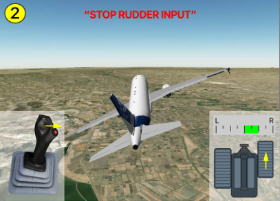
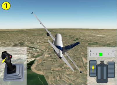
③ The PF then applied full left sidestick input and pressed the left rudder pedal to approximately halfway of its travel. The STOP RUDDER INPUT warning triggered again and the aircraft banked left. ④ The PF then applied full right sidestick and pressed the right rudder pedal causing the STOP RUDDER INPUT warning to trigger a third time and the aircraft to bank right.
(fig.2) Event description part 2
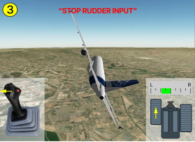
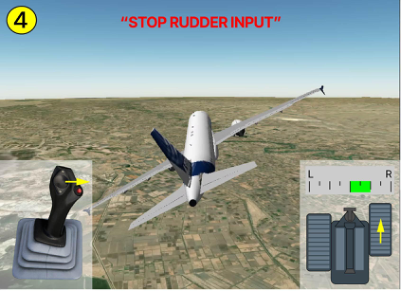
⑤ The PF briefly applied full left sidestick input and moved rudder pedals back to neutral position. The STOP RUDDER INPUT warning triggered for the fourth time. ⑥ The PF then managed to stabilize the aircraft using only light sidestick inputs.
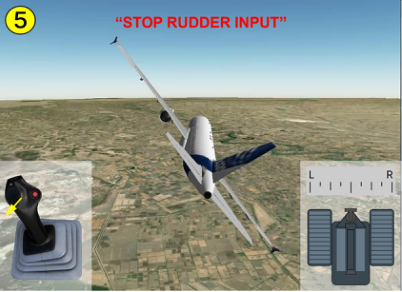
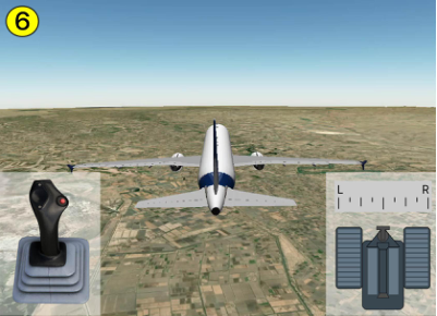
(fig.3) Event description part 3
The PF re-engaged the autopilot. The aircraft reached its cruise altitude 7 minutes later and the flight continued to its destination airport.
When the aircraft landed, the flight crew reported heavy turbulence to the maintenance but made no report of the STOP RUDDER INPUT warnings.
The Maintenance performed the AMM task 05-51-17 “INSPECTION AFTER FLIGHT IN EXCESSIVE TURBULENCE OR IN EXCESS OF VMO/MMO”, found no issues, and released the aircraft back into service.
Event Analysis
Section titled “Event Analysis”The event was not immediately reported after occurrence. Almost one year later, during routine data analysis, the unusual flight parameters were detected, prompting communication with the operator. Subsequently, a report was filed, allowing a detailed analysis to be performed.
Missed high lateral loads inspection
Section titled “Missed high lateral loads inspection”Analysis of the data confirmed a maximum lateral acceleration of 0.41 g during the event. This acceleration corresponds to a “red” level event according to AMM task 05-51-44 “INSPECTION AFTER FLIGHT WITH HIGH LATERAL LOADS”. However, only the AMM task 05-51-17 “INSPECTION AFTER FLIGHT IN EXCESSIVE TURBULENCE OR IN EXCESS OF VMO/MMO” was performed after the event based on the flight crewʼs report after the flight.
No excessive loads found
Section titled “No excessive loads found”The load analysis performed by Airbus using acceleration data concluded that flight loads were in the vicinity of design limits loads but did not exceed them. The correct maintenance tasks were subsequently performed, including AMM task 05-51-17 “INSPECTION AFTER FLIGHT IN EXCESSIVE TURBULENCE OR IN EXCESS OF VMO/MMO” and AMM task 05-51-44 “INSPECTION AFTER FLIGHT WITH HIGH LATERAL LOADS”. With no issues identified, the aircraft was confirmed as safe for return to service.
RUDDER DESIGN ON AIRBUS AIRCRAFT
Section titled “RUDDER DESIGN ON AIRBUS AIRCRAFT”Two types of rudder are installed on Airbus aircraft: mechanical rudder or electrical rudder.
Mechanical rudder
Section titled “Mechanical rudder”A mechanical rudder is installed on:
● A300 aircraft, ● A330-200/300 and ● A310 aircraft, A340-200/300 aircraft built before ● A320 family aircraft (except A321 July 2003 (mod 49144 not installed) XLR )
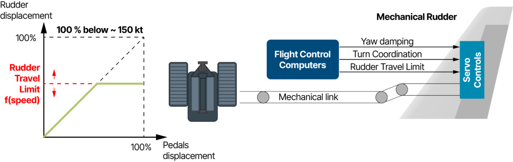
The rudder pedals are mechanically linked to the rudder servo controls (fig.4). Flight controls computers add correction inputs to the servo controls ensuring yaw damping, turn coordination, and a rudder travel limitation function to reduce rudder travel amplitude at high speed.
The rudder displacement is proportional to the pedals displacement until the rudder travel limit value is reached. Therefore, a limited rudder input at high speed can lead the rudder to reach its maximum travel limit.
(fig.4) Mechanical rudder
Electrical rudder
Section titled “Electrical rudder”An electrical rudder is installed on:
-
A220 aircraft ● A340-500/600
-
● A321 XLR aircraft aircraft
-
A330-200/300 and A340-200/300 ● A350 aircraft aircraft built after July 2003 (mod 49144 ● A380 aircraft installed)
-
● A330neo
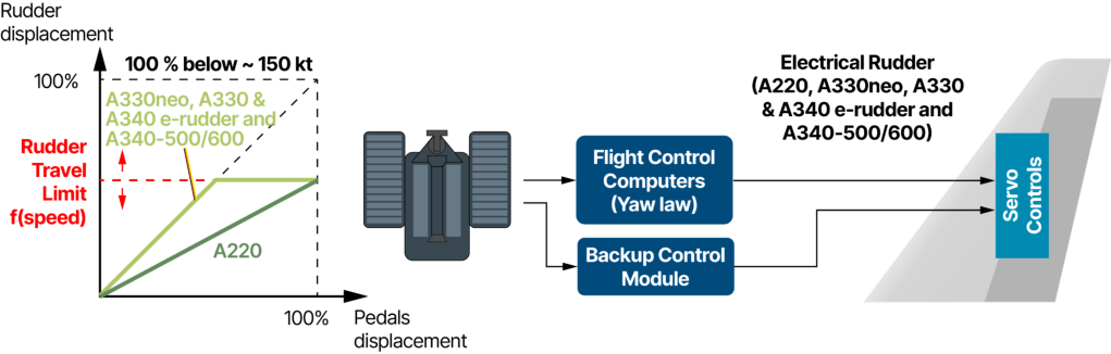
The rudder pedals send an electrical signal to the flight control computers (fig.5). There is no mechanical link between the rudder pedals and rudder servo controllers.
On A220, A330neo, A330 & A340 e-rudder and A340-500-600 aircraft , the pedal input is converted into an equivalent rudder deflection command to the servo controls. This command is adjusted to ensure yaw damping, turn coordination and rudder travel limitation.
On A330neo, A330 & A340 e-rudder and A340-500-600 aircraft, the rudder displacement is proportional to the pedals displacement until the rudder travel limit value is reached - the same design principle as aircraft with the mechanical rudder.
The pedals can be further pressed but the rudder will remain at its travel limit. At high speed, a very limited rudder pedal input can result in the rudder reaching its maximum travel limit.
On A220 aircraft, full pedal application needs to be used to reach the rudder travel limit.
A backup control module acts as a backup in the case of an electrical failure or a failure of the flight control computers.
(fig.5) Electrical rudder (A220, A330neo, A330 & A340 with e-rudder and A340-500/600 aircraft)
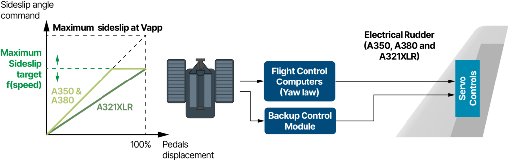
On A350, A380 and A321XLR aircraft , the rudder pedal input is converted into a sideslip angle target that varies depending on the flight phase (e.g. maximum sideslip on A350: 2° of sideslip at VMO and 15° in CONF 3 and FULL at approach speed (Vapp)). The yaw control law then sends a command to the servo controls to adjust the rudder position to achieve this sideslip angle target.
On A350 and A380, the sideslip target is proportional to the pedals displacement until the maximum sideslip target is reached. The pedals can be further pressed but the sideslip target will remain at the maximum sideslip target.
On A321XLR aircraft, full pedal application needs to be used to reach the maximum sideslip target.
(fig.6) Electrical rudder (A350, A380 and A321XLR aircraft)
Risks of Overload in the Case of Opposite Rudder Inputs
Section titled “Risks of Overload in the Case of Opposite Rudder Inputs”Aircraft structures are designed to sustain the loads caused by normal use of the rudder in a wide range of conditions and speeds. However, aggressive, rapid, full or nearly full travel, and rapidly pressing one rudder pedal then the other in opposite succession can lead to rudder inputs that will cause loads higher than the design limit, and can result in structural damage or failure. The rudder travel limit system is not designed to prevent potential structural damage or failure caused by such forceful rudder pedal inputs by the flight crew.
Even though aircraft with electrical rudder systems have flight control laws that may reduce the structural stress caused by forceful and alternating rudder pedal inputs, this should not be considered as protection against structural damage or failure due to such inputs.
“STOP RUDDER INPUT” Warning
Section titled ““STOP RUDDER INPUT” Warning”A STOP RUDDER INPUT aural alert combined with a message displayed on the PFD is available on A300/A310, A320 family aircraft (including A321 XLR), and A330/A340 aircraft equipped with mechanical rudder. It warns the flight crew when:
- Rudder pedals are at, or above, the position corresponding to the rudder travel limit
- Rudder pedals are then moved within a short timeframe (e.g. 3 s on A320 family) back to an almost neutral position and moved again in the same or opposite direction.
Taking the example of the event described previously, the PF first applied 22 % of left pedal input, which was above the 16 % position equivalent to the rudder travel limit at 290 kt (fig.6). The PF then applied 48% of right pedal input within 3s, causing the first STOP RUDDER INPUT warning.
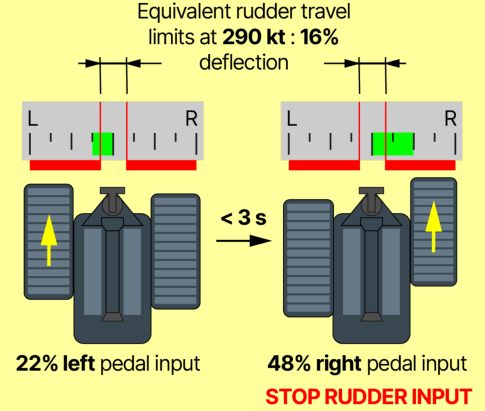
(fig.7) Example showing the conditions that caused the first STOP RUDDER INPUT warning during the previously described event involving an A320 family aircraft with a mechanical rudder
OPERATIONAL CONSIDERATIONS
Section titled “OPERATIONAL CONSIDERATIONS”| On all Airbus aircraft, regardless of the type of rudder installed on the aircraft |
|---|
| (mechanical or electrical)yaw damping and turn coordination are automated in |
| normal law. |
| The appropriate use of rudder pedals should be limited to the following |
| situations: |
| ground, |
| the rudder is trimmed. |
| The rudder pedals SHOULD NOT BE USED on Airbus aircraft for the following: |
| For more information on the handling of wake vortex encounters, refer to the |
| “Wake vortices” article published in January 2016 and updated in August 2024 |
| and to the “What about Wake Vortex in cruise?” video available on the WIN |
| website. |
Why Pilot Reporting of any High Load Event is Critical for Safety Pilots are the primary detectors of high load events, with their awareness and experience identifying potential loads that could lead to structural stress or damage concerns. Every pilot has the responsibility to document these events through appropriate logbook entries. Detailed information enables proper maintenance actions When reporting a high load event, whether caused by an excessive turbulence encounter or an excessive maneuvre, the flight crew must provide comprehensive information to maintenance personnel. This detailed reporting is essential as it enables maintenance teams to select and perform the appropriate inspections. If the rudder was used during the maneuvre, it must be specifically documented, particularly if the STOP RUDDER INPUT warning triggered during the flight. This critical information enables maintenance personnel to properly assess lateral loads and conduct necessary inspections, potentially preventing more serious structural issues from developing.
For more information on the reporting of high load events, refer to the “High Load Event Reporting” article published in March 2018.
MAINTENANCE CONSIDERATIONS
Section titled “MAINTENANCE CONSIDERATIONS”Ask for more information when needed
Section titled “Ask for more information when needed”Maintenance personnel should pay particular attention to pilot reports after an excessive turbulence or maneuver event. If these reports lack sufficient information, maintenance personnel should actively seek additional details from the flight crew. This follow-up is crucial to ensure that the appropriate AMM/MP/AMP is applied, unlike in the previously described event where AMM task 05-51-44 “INSPECTION AFTER FLIGHT WITH HIGH LATERAL LOADS” application was missed.
Specific A220 Maintenance Action
Section titled “Specific A220 Maintenance Action”On A220 aircraft AMP task BD500-A-J05-51-37-01AAA-284A-A “Extreme maneuver/severe turbulence event analysis (Technical data) - Special irregular inspection” requests that the maintenance team check both vertical and lateral acceleration loads are within limits.
Aircraft may not generate a LOAD<15> report
Section titled “Aircraft may not generate a LOAD<15> report”A320 family, A330 and A340 aircraft are equipped with LOAD<15> report capability that triggers in the case of a high load event. However, on A320 family aircraft, not all FDIMU standards are capable of detecting high lateral loads. Therefore on aircraft with FDIMU only capable of detecting vertical loads, a LOAD<15> report may not be triggered when only lateral loads occur. Additionally, even when both vertical and lateral loads are experienced, a generated LOAD<15> report might mention only the vertical loads. This limitation reinforces the critical importance of comprehensive pilot reporting.
If in doubt, check lateral loads using recorderʼs data
Section titled “If in doubt, check lateral loads using recorderʼs data”On all aircraft types, when there is uncertainty about the presence of lateral loads during an excessive turbulence event reported by flight crew, the maintenance personnel should apply the AMM/MP task 05-51-44 “INSPECTION AFTER FLIGHT WITH HIGH LATERAL LOADS” or the AMP task BD500-A-J05-51-37-01AAA-284A-A “Extreme maneuver/severe turbulence event analysis (Technical data) - Special irregular inspection”. These tasks guide how to assess the recorded lateral load, enabling appropriate maintenance actions to be taken if needed.
Contributors:
Section titled “Contributors:”Stephane DELANNOY
Section titled “Stephane DELANNOY”Flight Controls Development Design Office
Christophe DELMAS
Section titled “Christophe DELMAS”Aircraft Safety Enhancement Manager Design Office
Maxime LANSONNEUR
Section titled “Maxime LANSONNEUR”Director Safety - Training and Flight Operations Customer Support
Pierre-Henri MARCHETTI
Section titled “Pierre-Henri MARCHETTI”Abnormal Events & Multi-ATA Technical Leader
Damien GLEIZES
Section titled “Damien GLEIZES”Handling Qualities Engineer Design Office
With thanks to Laurent BUFFEL from the Flight Operations Data Analysis team, Tonino Colombo from the A220 Loads & Aeroelastics Engineering, Florence LE MARCHAND from Aviation Safety, Francis MEUNIER from the A220 Flight Characteristics and Louis THERIAULT from the A220 Flight Operations.
The use of rudder pedals by the flight crew on Airbus aircraft should be limited to the takeoff and landing roll, crosswind landings, or in the case of an engine failure until the rudder is trimmed. Using rudder inputs in other flight phases or during a turbulence encounter may cause unnecessary trajectory deviations and excessive loads on the aircraft structure.
The rudder travel limiter installed on Airbus aircraft protects the aircraft against static overload when the aircraft speed increases. However, aggressive, full or nearly full, opposite rudder pedal inputs can lead to loads exceeding the design limits, potentially resulting in structural damage or failure. While flight control laws on aircraft equipped with an electrical rudder may reduce the risk of overload in these situations, it should not be considered as comprehensive protection against potential damage from aggressive rudder pedal inputs.
It is essential that flight crews report excessive turbulence or excessive maneuvre events through detailed logbook entries. These reports must provide sufficient information to enable maintenance teams to assess the need for appropriate inspection procedures to confirm airworthiness. If rudder was used during the maneuvre, it must be specifically mentioned in the report, particularly if a “STOP RUDDER INPUT” warning occurred, so that the maintenance personnel can perform the AMM/MP/AMP inspection for high lateral loads.
In case of uncertainty about the presence of lateral loads during an excessive turbulence event reported by flight crew, the maintenance personnel should apply the AMM/MP task 05-51-44 “INSPECTION AFTER FLIGHT WITH HIGH LATERAL LOADS” or AMP task BD500-A-J05-51-37-01AAA-284A-A “Extreme maneuver / severe turbulence event analysis (Technical data) - Special irregular inspection” to analyse the recorded lateral loads and determine the appropriate actions to be carried out.
Safety first, 2025. Safety first is published by Airbus S.A.S. 1, rond point Maurice Bellonte - 31707 Blagnac Cedex/France.
Editor: Yannick Malinge, SVP Aviation Safety.
Editorial team: Guillaume Estragnat, Vanessa Sadi, Gwyneth Duggan, Javier Martinez Marina, Tim Roach.
Photos by Airbus.
来源:Airbus Safety First 网址:https://safetyfirst.airbus.com/use-of-rudder/ 发布日期:2025-04-28 类别:飞行运营、维护、侧风、高载荷、侧向载荷、颠簸、尾涡、尾涡湍流、偏航
空客飞机上,飞行机组对方向舵的使用仅限于起飞和着陆滑跑、侧风着陆,或在方向舵配平之前用于抵消发动机失效产生的偏航效应。据报告,发生过若干起飞行机组在遭遇颠簸后使用方向舵输入的事件,导致不必要的轨迹偏差和机体结构载荷。
本文描述了这样一起事件,并解释了空客飞机上使用的两种类型方向舵设计。同时,本文也为飞行机组提供了方向舵使用建议,并强调了事件发生后报告侧向载荷事件的重要性。此外,还为维护人员提供了指导,以确保在高载荷事件报告后执行必要的检查。
请在 safetyfirst.airbus.com 网站和适用于 iOS 和 Android 设备的 Safety first 应用上查看本文的最新版本。
一架空客 A320 飞机在 30 000 ft 高度,以自动推力(autothrust)和自动驾驶仪(autopilot)接通、在 MACH I、V/S +1000 和 NAV 模式下爬升,目标巡航高度为 36 000 ft。
穿越 31 200 ft 高度时,飞机开始向右滚转,并在数秒内达到 52°。① PF(飞行驾驶员)反应为:完全向左的侧杆输入且机头向上,导致自动驾驶仪脱开,并轻踩左方向舵。这些组合控制输入使飞机向左倾斜。② PF 迅速反应,通过施加完全向右的侧杆输入,并将右方向舵踏板踩至约一半行程。此举导致飞机剧烈向右倾斜,并触发 STOP RUDDER INPUT(停止方向舵输入) 警告。
(图 1) 事件描述第一部分
③ PF 随即施加完全向左的侧杆输入,并将左方向舵踏板踩至约一半行程。STOP RUDDER INPUT 警告再次触发,飞机向左倾斜。④ PF 接着施加完全向右的侧杆并踩下右方向舵踏板,导致 STOP RUDDER INPUT 警告第三次触发,飞机向右倾斜。
(图 2) 事件描述第二部分
⑤ PF 短暂施加完全向左的侧杆输入,并将方向舵踏板回到中立位置。STOP RUDDER INPUT 警告第四次触发。⑥ PF 随即仅使用轻度的侧杆输入使飞机稳定下来。
(图 3) 事件描述第三部分
PF 重新接通了自动驾驶仪。飞机 7 分钟后到达巡航高度,航班继续飞往目的地机场。
飞机着陆后,飞行机组向维修部门报告了严重颠簸,但未报告 STOP RUDDER INPUT 警告。
维修部门执行了 AMM 任务 05-51-17“在严重颠簸中飞行或超过 VMO/MMO 后的检查”,未发现问题,并将飞机恢复使用。
该事件未在发生后立即报告。近一年后,在例行数据分析中发现了异常的飞行参数,促使与运营方取得联系。随后提交了报告,使详细分析得以进行。
遗漏的高侧向载荷检查
Section titled “遗漏的高侧向载荷检查”数据分析确认,事件期间最大侧向加速度为 0.41 g。根据 AMM 任务 05-51-44“在高侧向载荷下飞行后的检查”,该加速度对应“红色”级别事件。然而,事件后仅根据飞行机组着陆后的报告执行了 AMM 任务 05-51-17“在严重颠簸中飞行或超过 VMO/MMO 后的检查”。
未发现超限载荷
Section titled “未发现超限载荷”空客使用加速度数据进行的载荷分析得出结论:飞行载荷在设计极限载荷附近,但未超过。后续执行了正确的维护任务,包括 AMM 任务 05-51-17“在严重颠簸中飞行或超过 VMO/MMO 后的检查” 和 AMM 任务 05-51-44“在高侧向载荷下飞行后的检查”。经检查未发现问题,确认飞机可以安全恢复运营。
空客飞机上的方向舵设计
Section titled “空客飞机上的方向舵设计”空客飞机上安装了两类方向舵:机械式方向舵或电动式方向舵。
机械式方向舵
Section titled “机械式方向舵”机械式方向舵安装在:
● A300 飞机,● A330-200/300 及● A310 飞机,● 2003年7月之前生产的 A340-200/300 飞机● A320 系列飞机(除 A321 XLR 飞机(未安装改装件49144)之外)
方向舵脚蹬通过机械连杆与方向舵伺服控制装置相连 (图4)。飞行控制计算机向伺服控制装置添加修正输入,以确保偏航阻尼、转弯协调以及方向舵行程限制功能,从而在高速飞行时减小方向舵行程幅度。
方向舵偏转量与脚蹬偏转量成正比,直至达到方向舵行程限制值。 因此,在高速飞行时,有限的方向舵输入即可使方向舵达到其最大行程限制。
(图4) 机械式方向舵
电动式方向舵
Section titled “电动式方向舵”电动式方向舵安装在:
-
A220 飞机● A340-500/600
-
● A321 XLR 飞机
-
A330-200/300 及 A340-200/300 ● A350 飞机 2003年7月之后生产的飞机(改装件49144 ● A380 飞机已安装)
-
● A330neo
方向舵脚蹬向飞行控制计算机发送电信号 (图5)。方向舵脚蹬与方向舵伺服控制器之间无机械连接。
在 A220、A330neo、A330 & A340 电驱方向舵以及 A340-500-600 飞机上,脚蹬输入被转换为等效的方向舵偏转指令发送给伺服控制装置。该指令经过调整以确保偏航阻尼、转弯协调和方向舵行程限制。
在 A330neo、A330 & A340 电驱方向舵以及 A340-500-600 飞机上,方向舵偏转量与脚蹬偏转量成正比,直至达到方向舵行程限制值——与机械式方向舵飞机相同的设计原理。
脚蹬可以继续踩压,但方向舵将保持在行程限制位置。在高速飞行时,非常有限的方向舵脚蹬输入即可导致方向舵达到其最大行程限制。
在 A220 飞机上,需要施加全行程脚蹬输入才能达到方向舵行程限制。
备份控制模块在发生电气故障或飞行控制计算机故障时充当备份。
(图5) 电动式方向舵(A220、A330neo、A330 & A340 电驱方向舵及 A340-500/600 飞机)
在 A350、A380 和 A321XLR 飞机上,方向舵脚蹬输入被转换为侧滑角目标值,该目标值根据飞行阶段而变化(例如 A350 最大侧滑:在 VMO 时为 2° 侧滑角,在 CONF 3 和 FULL 构型且进近速度(Vapp)时为 15°)。偏航控制律随后向伺服控制装置发送指令,以调整方向舵位置来达到该侧滑角目标。
在 A350 和 A380 上,侧滑目标值与脚蹬偏转量成正比,直至达到最大侧滑目标值。脚蹬可以继续踩压,但侧滑目标值将保持在最大侧滑目标值。
在 A321XLR 飞机上,需要施加全行程脚蹬输入才能达到最大侧滑目标值。
(图6) 电动式方向舵(A350、A380 和 A321XLR 飞机)
相反方向舵输入导致的过载风险
Section titled “相反方向舵输入导致的过载风险”飞机结构设计能够承受在各种条件和速度下正常使用方向舵所产生的载荷。然而,激进、快速、全行程或接近全行程的方向舵输入,以及快速交替踩压两侧方向舵脚蹬,可能导致方向舵输入产生的载荷超过设计极限,从而造成结构损伤或失效。方向舵行程限制系统并非设计用于防止此类强力方向舵脚蹬输入可能造成的结构损伤或失效。
尽管配备电动式方向舵系统的飞机具有飞行控制律,可能减轻因强力及交替方向舵脚蹬输入而造成的结构应力,但不应将此视为对因此类输入而导致结构损伤或失效的保护措施。
“STOP RUDDER INPUT”(停止方向舵输入)警告
Section titled ““STOP RUDDER INPUT”(停止方向舵输入)警告”STOP RUDDER INPUT 音响警告配合 PFD 上显示的信息适用于配备机械式方向舵的 A300/A310、A320 系列飞机(包括 A321 XLR)和 A330/A340 飞机。该警告在以下情况下提醒飞行机组:
- 方向舵脚蹬处于或超过与方向舵行程限制对应的位置
- 然后在短时间内(例如 A320 系列飞机 3 秒内)将方向舵脚蹬移回接近中立的位置,并再次向同一方向或相反方向踩踏。
以之前描述的事件为例,副驾驶首先施加了 22% 的左侧脚蹬输入,超过 290 kt 时相当于方向舵行程限制的 16% 位置 (图 6)。副驾驶随后在 3 秒内施加了 48% 的右侧脚蹬输入,触发了第一次方向舵输入停止警告。
(图 7) 示例展示了在上述 A320 系列飞机机械方向舵事件中导致第一次方向舵输入停止警告的条件
运行注意事项
Section titled “运行注意事项”| 在所有空客飞机上,无论飞机上安装的是何种类型方向舵 |
|---|
| (机械或电传)偏航阻尼和转弯协调在正常法则下是自动化的。 |
| 方向舵脚蹬应仅限于以下情况使用: |
| 地面, |
| 方向舵已配平。 |
| 在空客飞机上,方向舵脚蹬不应用于以下情况: |
| 有关尾涡遭遇的处理方法,请参阅 |
| 2016 年 1 月发布并于 2024 年 8 月更新的 |
| ”尾涡”文章,以及 WIN 网站上提供的 |
| ”巡航中的尾涡怎么办?“视频。 |
为什么飞行员报告任何高载荷事件对安全至关重要 飞行员是高载荷事件的主要发现者,他们的意识和经验能够识别可能导致结构应力或损坏顾虑的潜在载荷。每位飞行员都有责任通过适当的飞行日志记录来记录这些事件。详细信息能够确保正确的维护措施 在报告高载荷事件时,无论是由于过度颠簸还是过度机动造成的,机组人员必须向维护人员提供全面的信息。这种详细报告至关重要,因为它使维护团队能够选择并执行适当的检查。如果在机动过程中使用了方向舵,必须特别记录,特别是如果在飞行中触发了方向舵输入停止警告。这一关键信息使维护人员能够正确评估侧向载荷并进行必要的检查,有可能防止更严重的结构问题发生。
有关高载荷事件报告的更多信息,请参阅 2018 年 3 月发布的”高载荷事件报告”文章。
维护注意事项
Section titled “维护注意事项”需要时主动询问更多信息
Section titled “需要时主动询问更多信息”维护人员应特别关注过度颠簸或机动事件后的飞行员报告。如果这些报告缺乏足够的信息,维护人员应主动从机组人员处获取更多细节。这一后续跟进对于确保应用适当的 AMM/MP/AMP 至关重要,这与之前描述的事件不同,在该事件中 AMM 任务 05-51-44”高侧向载荷飞行后的检查” 的应用被遗漏。
A220 specific 维护措施
Section titled “A220 specific 维护措施”在 A220 飞机上,**AMP 任务 BD500-A-J05-51-37-01AAA-284A-A”极端机动/严重颠簸事件分析(技术数据)- 特殊不规则检查”**要求维护团队检查垂直和侧向加速载荷均在限制范围内。
飞机可能不会生成 LOAD<15> 报告
Section titled “飞机可能不会生成 LOAD<15> 报告”A320 系列、A330 和 A340 飞机配备了在高载荷事件时触发的 LOAD<15> 报告功能。但是,**在 A320 系列飞机上,并非所有 FDIMU 标准都能够检测高侧向载荷。**因此,在仅能检测垂直载荷的 FDIMU 飞机上,当仅发生侧向载荷时可能不会触发 LOAD<15> 报告。此外,即使经历了垂直和侧向载荷,生成的 LOAD<15> 报告可能仅提及垂直载荷。这一限制强化了全面飞行员报告的至关重要性。
如有疑问,使用记录器数据检查侧向载荷
Section titled “如有疑问,使用记录器数据检查侧向载荷”在所有机型上,当飞行机组报告的剧烈颠簸事件是否存在侧向载荷存在不确定性时,维护人员应执行 AMM/MP 任务 05-51-44“承受高侧向载荷后的检查” 或 AMP 任务 BD500-A-J05-51-37-01AAA-284A-A“极端机动/严重颠簸事件分析(技术数据)——特殊非例行检查”。 这些任务指导如何评估记录的侧向载荷,以便在需要时采取适当的维护措施。
Stephane DELANNOY
Section titled “Stephane DELANNOY”飞行控制研发设计办公室
Christophe DELMAS
Section titled “Christophe DELMAS”飞机安全增强经理设计办公室
Maxime LANSONNEUR
Section titled “Maxime LANSONNEUR”客户支持培训与飞行运营安全总监
Pierre-Henri MARCHETTI
Section titled “Pierre-Henri MARCHETTI”异常事件与多 ATA 技术负责人
Damien GLEIZES
Section titled “Damien GLEIZES”设计办公室品质特性工程师
特别感谢 Flight Operations Data Analysis 团队的 Laurent BUFFEL、A220 Loads & Aeroelastics Engineering 的 Tonino Colombo、Aviation Safety 的 Florence LE MARCHAND、A220 Flight Characteristics 的 Francis MEUNIER 以及 A220 Flight Operations 的 Louis THERIAULT。
空客飞机上的飞行机组使用方向舵脚蹬应限于起飞和着陆滑跑、侧风着陆,或在发动机失效后直至方向舵配平完成。在其他飞行阶段或遭遇颠簸时使用方向舵输入可能导致不必要的轨迹偏差和飞机结构过载。
安装在空客飞机上的方向舵行程限制器可在飞机速度增加时保护飞机免受静力过载。然而,剧烈、满行程或接近满行程的反向方向舵脚蹬输入可能导致超过设计限制的载荷,从而可能造成结构损伤或失效。虽然装有电动方向舵的飞机的飞行控制法则可能会降低这些情况下的过载风险,但不应将其视为对剧烈方向舵脚蹬输入可能造成损伤的全面保护。
飞行机组必须通过详细的飞行日志记录报告剧烈颠簸或剧烈机动事件。这些报告必须提供足够的信息,使维护团队能够评估执行适当检查程序以确认适航性的必要性。如果在机动中使用了方向舵,必须在报告中特别提及,特别是如果发生了”STOP RUDDER INPUT”(停止方向舵输入)警告,以便维护人员能够执行 AMM/MP/AMP 关于高侧向载荷的检查。
如果飞行机组报告的剧烈颠簸事件是否存在侧向载荷存在不确定性,维护人员应执行 AMM/MP 任务 05-51-44”承受高侧向载荷后的检查”或 AMP 任务 BD500-A-J05-51-37-01AAA-284A-A”极端机动/严重颠簸事件分析(技术数据)——特殊非例行检查”,以分析记录的侧向载荷并确定需执行的适当措施。
Safety first, 2025. Safety first 由空中客车 S.A.S. 出版,地址:1, rond point Maurice Bellonte - 31707 Blagnac Cedex/France。
编辑:Yannick Malinge,航空安全高级副总裁。
编辑团队:Guillaume Estragnat、Vanessa Sadi、Gwyneth Duggan、Javier Martinez Marina、Tim Roach。
照片由空客提供。