Do not Wait to Apply the Engine Fire Procedure
Source: Airbus Safety First URL: https://safetyfirst.airbus.com/do-not-wait-to-apply-the-engine-fire-procedure/ Published: 2022-05-27 Category: Flight Ops, extinguisher, tailpipe fire PDF: Original PDF

Several recent engine fire events highlight the importance of timely application of the engine fire procedure.
This article explains why flight crew must apply this procedure without delay. Decisive action when there is an engine fire alert may prevent further damage to the This can to ensure that a engine. help manageable fire situation does not become an uncontrolled with more fire serious consequences.
This article is also available on safetyfrst.airbus.com and on the Safety first app for iOS and Android devices.
CASE STUDY
Section titled “CASE STUDY”Event Description
Section titled “Event Description”An A330 aircraft departed for a long-range flight. The aircraft was in CONF 2 for the takeoff. The takeoff roll was normal, but the ENG 2 FIRE red ECAM alert triggered (T0) 17 s after liftoff. The flight crew continued the climb. The engine display showed stable engine parameters for both engines.
At T0 + 51 s, the aircraft reached 2 400 ft RA. The PF set the engine 2 thrust lever to IDLE and pushed the engine 1 thrust lever to TOGA.
At T0 + 52 s, the PF set the engine 1 thrust lever to MCT and this caused the autothrust to engage in thrust mode.
At T0 + 2 min 27 s , the flight crew set the engine 2 master lever to OFF.
At T0 + 2 min 43 s, the flight crew pressed the ENG FIRE pushbutton and discharged AGENT 1 followed by AGENT 2. The ENG 2 FIRE alert remained after both agents were discharged.
At T0 + 3 min 38 s , the flight crew engaged the autopilot and leveled off the aircraft at 7 000 ft.
At T0 + 6 min 31 s , the flight crew started the APU, which provided the electrical power supply to the right side.
At T0 + 9 min 39 s , the EGT indication for engine 2 started to increase, even though it had shown decreasing EGT from the time when the engine 2 master lever was set to OFF.
At T0 + 10 min 03 s , the ENG 2 FIRE alert stopped and the ENG 2 FIRE DET FAULT amber ECAM alert triggered.
At T0 + 11 min 23 s , the ENG 2 EGT OVERLIMIT amber ECAM alert triggered when engine 2 EGT reached 600 °C.
At T0 + 15 min 09 s , the engine 2 N1 value became invalid.
At T0 + 17 min 35 s , the engine 2 EGT reached a peak value of 801 °C.
At T0 + 25 min 02 s , the aircraft touched down on the runway and safely came to a stop. Smoke and flames coming from engine 2 were seen. The fire brigade arrived and extinguished the fire.

Event Analysis
Section titled “Event Analysis”Probable cause identified
Section titled “Probable cause identified”Investigation enabled Airbus to conclude that the most probable cause of the engine fire was a leak from the green hydraulic circuit, which may have been due to damage on a green hydraulic line during maintenance.
Delayed application of the fire procedure
Section titled “Delayed application of the fire procedure”Any red ECAM alert requires immediate action by the flight crew to ensure the continued safety of the flight. When the ENG X FIRE alert is triggered, a red LAND ASAP memo appears on the ECAM. This requires that the flight crew land as soon as possible at the nearest airport at which a safe landing can be made.
During this event, the engine 2 thrust lever was not set to IDLE until 51s after the ENG 2 FIRE alert was triggered. A further 1m 36s passed (T0 + 2m 27s) before the ENG FIRE procedure was completed to isolate the fire and use the fire extinguishing system.
Nominal engine parameter despite the fire
Section titled “Nominal engine parameter despite the fire”The engine indications in the cockpit appeared to show that engine 2 operation was normal. This may have been a factor in the flight crew’s decision to delay application of the engine fire procedure.
Remaining fire and further propagation
Section titled “Remaining fire and further propagation”Analysis showed that the engine fire extinguishing system operated as intended and both extinguisher bottles correctly discharged during the event. It is likely that the fire reignited shortly after extinction due to remaining conditions for fire reignition in the nacelle.
The EGT increased up to 801 °C, which is a sign that the fire spread toward the EGT thermocouples. The fire continued to cause destruction of the fire detection loops and damage to wiring. This was the reason the ENG 2 FIRE ECAM alert stopped and was replaced by the ENG 2 FIRE DET FAULT amber alert. Note that this alert was in the overflow part of the warning display, indicated by a green arrow.
Similarly, the loss of the N1 information was due to damage to wiring.
TWO TYPES OF ENGINE FIRE
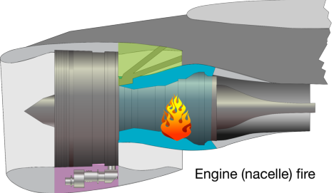
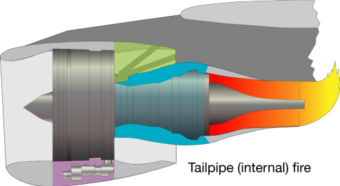
Section titled “TWO TYPES OF ENGINE FIRE”There are two types of engine fire (fig.1) : an engine fire (nacelle fire) and tailpipe fire (internal fire) . Both types of fire affect the engine, but must be treated differently.
Engine fire (nacelle fire)
Section titled “Engine fire (nacelle fire)”An engine fire affects the external part of the engine core, but is contained within the engine nacelle. This type of fire can occur on ground or in flight and is usually caused by a malfunction or rupture of a component or pipe, which contains flammable liquids (e.g. fuel, oil, hydraulic fluid). When these liquids come into contact with hot surfaces on the engine case, such as the high pressure compressor, combustor, or turbine, they can self-ignite and cause a fire. This type of engine fire can also be caused by rupture of a part of the engine core causing damage to components and pipes, which can lead to a fire.
The engine fire protection system will detect the fire and trigger the red ENG X FIRE ECAM alert (L ENG FIRE or R ENG FIRE on A220 aircraft). The flight crew must apply the associated engine fire procedure without delay.
Tailpipe fire (internal fire)
Section titled “Tailpipe fire (internal fire)”A tailpipe fire occurs inside the engine core. This type of fire will only occur during the engine start or shutdown sequence. A tailpipe fire occurs when the engine rotates at a very low speed and residual fuel is present in the combustion chamber or turbine area, or if there is an oil leak in the tailpipe of the engine. The risk of tailpipe fire is higher in the case of a second engine start attempt, because residual fuel may remain in the engine after the first attempted engine start.
The fire detection system does not detect tailpipe fires, because they occur inside the hot sections of the engine core, and therefore, are outside of the fire detection zone. Flight crews can detect tailpipe fires by observing any abnormal increase in EGT during the engine start sequence or if the EGT does not decrease after engine shutdown. Ground crew, cabin crew, or air traffic controllers may also observe a tailpipe fire and must inform the flight crew.
In the case of a tailpipe fire, the flight crew must apply the ENGINE TAILPIPE FIRE abnormal procedure from the QRH. This will ventilate the engine, and the airflow will extinguish the fire and remove any residual fuel or vapor from the engine. On the A220, a tailpipe fire procedure is under study to be introduced in the QRH/FCOM.
After any tailpipe fire, inspection by maintenance is required to check that there is no flame damage to the flaps, wing, or pylon areas.
(fig.1) Engine fire vs Tailpipe fire
RELY ON THE ENGINE FIRE ALERT
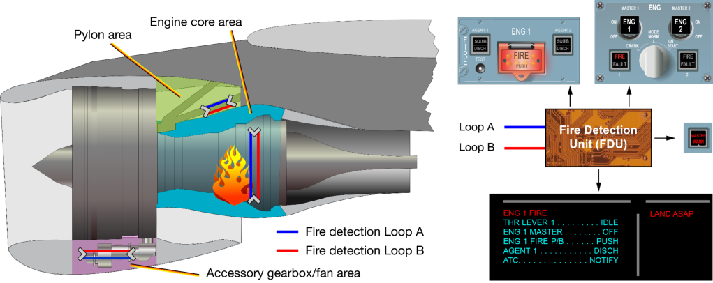
Section titled “RELY ON THE ENGINE FIRE ALERT”The detection system for engine fire is composed of dual sensing element loops. They are located in the areas around the engine with the highest risk of fire and near compartment air exhausts for overheat detection. These are zones where flammable liquids are present with a potential ignition source, such as the accessory gearbox area, the pylon area above the combustion chamber, the combustion chamber area, and the fan area on certain engines. Each loop is doubled (loop A and loop B) for redundancy purposes. The loops can detect fire or hot air leaks.
The dual sensing element loops are monitored by a Fire Detection Unit (FDU) (A300/A310/A320 family/A330/A340 and A380 aircraft), the Fire Protection Function hosted in CPIOMs J (A350 aircraft), or the Fire Detection and EXtinguishing (FIDEX) Control Unit (A220 aircraft).
Reliability of the engine fire detection system
Section titled “Reliability of the engine fire detection system”The design and redundancy of the detection loops ensure a high level of reliability for the engine fire detection system. In the event of an engine fire alert, the flight crew must rely on it.
(fig.2) Example of engine fire detection system on an A320 aircraft with CFM engines
Engine parameters may remain normal during an engine fire
Section titled “Engine parameters may remain normal during an engine fire”Flight crews must be aware that engine thrust and engine parameters can remain normal in the early stage of an engine fire. The event described in this article is illustrative of this fact.
In the event of an engine fire alert, the flight crew must apply the procedure even if the engine thrust is stable and the engine parameters are normal on the engine display and on the engine SD page.
Apply the engine fire procedure without delay
Section titled “Apply the engine fire procedure without delay”The architecture of the nacelle is designed to contain the fire threat for a minimum, but also limited time. Therefore, the flight crew must apply the engine fire procedure without delay when there is an engine fire alert.
Timely application of the engine fire procedure will limit fire propagation and prevent further damage to components or pipes around the engine core. Such damage could cause additional leaks of flammable fluids, which could increase the intensity or duration of the fire.
The use of autopilot in the case of an engine fire alert reduces crew workload and enables a safe handling of the thrust asymmetry that is induced when thrust is reduced on the affected engine. Therefore, the flight crew can apply the ECAM procedure earlier and under less stress. This is particularly useful in phases of flight with a high workload, such as initial climb and the approach phase.
Detection fault and fire propagation
Section titled “Detection fault and fire propagation”The event described in this article shows how a fire can propagate and damage the fire protection loops, which caused the engine fire warning to stop and be replaced by a fire detection amber fault. As a precaution, the flight crew should interpret a replacement of the ENG X FIRE red alert by an ENG X FIRE DET FAULT amber alert as the sign of a potential propagating fire. ENG X FIRE can similarly be replaced by both LOOP ENG X LOOP A FAULT and LOOP ENG X LOOP B FAULT on A300-600/A310 aircraft. On A220 aircraft, L ENG FIRE DET FAIL or R ENG FIRE DET FAIL can replace the L ENG FIRE or R ENG FIRE alert.
Steps of the Engine Fire Procedure
Section titled “Steps of the Engine Fire Procedure”Step 1: Engine shutdown
Section titled “Step 1: Engine shutdown”The first step of the engine fire procedure is to set the thrust lever of the affected engine to idle and set its master switch to OFF. This will cut the fuel supply to the affected engine by closing the HP and LP fuel valves.
Step 2: Engine isolation
Section titled “Step 2: Engine isolation”The second step is to press the FIRE pushbutton for the affected engine, in order to completely isolate the engine from the fuel, electrical, hydraulic, and pneumatic systems. This is to prevent further damage or fire propagation and prevent smoke from entering the air conditioning system.
Step 3: Fire extinguishing
Section titled “Step 3: Fire extinguishing”The third step is to extinguish the fire by discharging the fire agents into the nacelle one after the other when in flight or simultaneously when on the ground (On A220, on the ground, the procedure also requests to discharge the agent one after the other). The 10 s delay requested by the ECAM procedure to discharge agent 1 in flight enables N1 to decrease. This will reduce ventilation of the nacelle, so that the fire extinguishing agent is more effective.
The flight crew must complete the procedure and discharge the agents as long as the engine fire alert is displayed and the FIRE lights are still ON on the overhead panel and pedestal.
Contributors:
Section titled “Contributors:”Stéphane COTE Accident/Incident Investigator Product Safety
Emmanuel JANSSEN
Section titled “Emmanuel JANSSEN”Pilot Instructor Training and Flight Operations Support
Franco MONTELEONE
Section titled “Franco MONTELEONE”Head of A220 Propulsion system A220 Design Office
Stéphane PUGLIESE
Section titled “Stéphane PUGLIESE”Expert Fire Prevention & Protection Design Office
Aircraft engines are equipped with a reliable fire detection system. Flight crews must be aware that in the event of an engine fire alert, the engine parameters can remain normal in the early stage of the fire. Therefore, the flight crew must apply the ECAM/EICAS procedure without delay, even if the engine display and engine SD page display nominal parameters.
Timely application of the engine fire procedure limits propagation of the fire and prevents further damage to components or pipes around the engine core that may create additional leaks of flammable fluids and increase the intensity or duration of the fire.
The flight crew must complete the engine fire procedure and discharge the agents as long as the engine fire alert is displayed and the FIRE lights are still ON on the overhead panel and pedestal.
By taking decisive action when there is an engine fire alert, the flight crew can prevent a manageable fire situation from becoming an uncontrolled fire with more serious consequences.
Michel RICHARME Synthetic Flight Instructor Training and Flight Operations Support
With thanks to Christophe MATHE and Thomas GOBEAUT from Flight Operations Support
Safety first, 2022. Safety first is published by Airbus S.A.S. 1, rond point Maurice Bellonte - 31707 Blagnac Cedex/France.
Editor: Yannick Malinge, Chief Product Safety Officer.
Editorial team: Guillaume Estragnat, Vanessa Sadi, Gwyneth Duggan, Tim Roach.
- Reference: X00D16031905.
Photos by Airbus.
来源:Airbus Safety First 网址:https://safetyfirst.airbus.com/do-not-wait-to-apply-the-engine-fire-procedure/ 发布日期:2022-05-27 类别:飞行操作,灭火器,尾喷口失火 PDF:原始 PDF
近期多起发动机失火事件表明,及时执行发动机失火程序至关重要。
本文将解释为何飞行机组必须毫不迟疑地执行该程序。当出现发动机失火警戒时,采取果断措施可以防止发动机进一步受损。这有助于确保可控的失火情况不会演变为更具危害性的失控失火。
本文亦可在 safetyfrst.airbus.com 及 iOS 和 Android 版 Safety first 应用中获取。
一架 A330 飞机起飞执行远程航班。起飞时使用 CONF 2 形态。起飞滑跑正常,但在离地后 (T0) 17 秒,触发 ENG 2 FIRE 红色 ECAM 警戒。飞行机组继续爬升。发动机参数显示两台发动机参数均稳定。
T0 + 51 秒, 飞机到达 2 400 ft RA。PF 将 2 号发动机推力手柄设置到 IDLE,并将 1 号发动机推力手柄推到 TOGA。
T0 + 52 秒, PF 将 1 号发动机推力手柄设置到 MCT,这导致自动推力以推力模式接通。
T0 + 2 分 27 秒, 飞行机组将 2 号发动机主电门设置到 OFF。
T0 + 2 分 43 秒, 飞行机组按下 ENG FIRE 按压电门,释放 AGENT 1,随后释放 AGENT 2。释放两个灭火剂后,ENG 2 FIRE 警戒仍然存在。
T0 + 3 分 38 秒, 飞行机组接通自动驾驶仪,将飞机在 7 000 ft 平飞。
T0 + 6 分 31 秒, 飞行机组启动 APU,APU 为右侧提供电力。
T0 + 9 分 39 秒, 2 号发动机的 EGT 指示开始上升,尽管在 2 号发动机主电门设置到 OFF 后 EGT 已经开始下降。
T0 + 10 分 03 秒, ENG 2 FIRE 警戒停止,触发 ENG 2 FIRE DET FAULT 琥珀色 ECAM 警戒。
T0 + 11 分 23 秒, 当 2 号发动机 EGT 达到 600 °C 时,触发 ENG 2 EGT OVERLIMIT 琥珀色 ECAM 警戒。
T0 + 15 分 09 秒, 2 号发动机 N1 值变为无效。
T0 + 17 分 35 秒, 2 号发动机 EGT 达到峰值 801 °C。
T0 + 25 分 02 秒, 飞机在跑道上接地并安全停止。目视可见 2 号发动机冒出烟雾和火焰。消防队到场后扑灭了火灾。
已识别的可能原因
Section titled “已识别的可能原因”调查使空客得出结论,发动机失火的最可能原因是绿色液压管路泄漏,可能是由于维护期间绿色液压管路受损所致。
延迟执行失火程序
Section titled “延迟执行失火程序”任何红色 ECAM 警戒都需要飞行机组立即采取行动以确保飞行持续安全。当触发 ENG X FIRE 警戒时,ECAM 上会出现红色 LAND ASAP 备忘。这意味着飞行机组必须尽快在能够安全着陆的最近机场落地。
在此次事件中,在 ENG 2 FIRE 警戒触发后 51 秒才将 2 号发动机推力手柄设置到 IDLE。又过了 1 分 36 秒(T0 + 2 分 27 秒),才完成 ENG FIRE 程序以隔离失火并使用灭火系统。
失火期间发动机参数正常
Section titled “失火期间发动机参数正常”驾驶舱中的发动机指示显示 2 号发动机运行似乎正常。这可能是导致飞行机组延迟执行发动机失火程序的一个因素。
持续失火及进一步蔓延
Section titled “持续失火及进一步蔓延”分析表明,发动机灭火系统按预期运行,两个灭火瓶在事件期间正确释放。由于短舱内仍存在复燃条件,失火可能在熄灭后不久重新点燃。
EGT 升高至 801 °C,表明火势已蔓延至 EGT 热电偶。火灾持续导致失火探测环路损毁和线路损坏。这就是 ENG 2 FIRE ECAM 警戒停止并被 ENG 2 FIRE DET FAULT 琥珀色警戒取代的原因。请注意,此警戒位于警告显示的溢出区域,由绿色箭头指示。
同样,N1 信息的丢失也是由于线路损坏所致。
两种类型的发动机火警
Section titled “两种类型的发动机火警”有两种类型的发动机火警 (图1):发动机火警(发动机舱火警)和尾管火警(内部火警)。两种类型的火警都会影响发动机,但必须采用不同的方式处理。
发动机火警(发动机舱火警)
Section titled “发动机火警(发动机舱火警)”发动机火警影响核心机的外部部分,但被限制在发动机舱内。这种火警可能在地面或飞行中发生,通常由含有易燃液体(例如燃油、润滑油、液压油)的部件或管道的故障或破裂引起。当这些液体接触到发动机机匣上的高温表面(如高压压缩机、燃烧室或涡轮)时,它们可能自燃并引发火灾。这种类型的发动机火警也可能是由核心机部件破裂导致,从而损坏部件和管道,进而引发火灾。
发动机火警保护系统将探测到火警并触发红色 ENG X FIRE ECAM 警告(A220 飞机上为 L ENG FIRE 或 R ENG FIRE)。机组必须毫不迟疑地执行相应的发动机火警程序。
尾管火警(内部火警)
Section titled “尾管火警(内部火警)”尾管火警发生在核心机内部。这种火警仅在发动机启动或关车序列期间发生。当发动机以极低转速旋转且燃烧室或涡轮区域存在残余燃油,或发动机尾管存在滑油泄漏时,就会发生尾管火警。在第二次启动发动机的情况下,尾管火警的风险更高,因为首次启动失败后发动机内可能残留燃油。
火警探测系统无法探测到尾管火警,因为它们发生在核心机的高温区域,因此位于火警探测区之外。机组可以通过观察发动机启动序列中排气温度(EGT)的异常升高,或在发动机关车后 EGT 不下降来探测尾管火警。地面人员、客舱乘务组或空中交通管制员也可能观察到尾管火警,并必须通知机组。
对于尾管火警,机组必须执行 QRH 中的 ENGINE TAILPIPE FIRE(非正常程序)。这将通风发动机,气流将扑灭火警并清除发动机内残余的燃油或蒸汽。在 A220 上,尾管火警程序正在研究中,将在 QRH/FCOM 中引入。
任何尾管火警之后都需要维护检查,以确认襟翼、机翼或挂架区域没有火焰损伤。
(图1) 发动机火警与尾管火警
依靠发动机火警警告
Section titled “依靠发动机火警警告”发动机火警探测系统由双传感元件环路组成。这些环路位于发动机周围火警风险最高的区域,以及用于过热探测的舱室排气口附近。这些是存在易燃液体和潜在点火源的区域,例如附件齿轮箱区域、燃烧室上方的吊架区域、燃烧室区域以及某些发动机上的风扇区域。每个环路都有备份(A 环路和 B 环路)以提供冗余。环路可以探测火警或热空气泄漏。
双传感元件环路由火警探测组件(FDU)(A300/A310/A320 系列/A330/A340 和 A380 飞机)、托管在 CPIOM J 中的火警保护功能(A350 飞机)或火警探测与灭火(FIDEX)控制组件(A220 飞机)监控。
发动机火警探测系统的可靠性
Section titled “发动机火警探测系统的可靠性”探测环路的设计和冗余确保了发动机火警探测系统的高可靠性。发生发动机火警警告时,机组必须依靠它。
(图2) A320 飞机(配备 CFM 发动机)发动机火警探测系统示例
发动机参数在发动机火警期间可能保持正常
Section titled “发动机参数在发动机火警期间可能保持正常”机组必须注意,在发动机火警的早期阶段,发动机推力和发动机参数可能保持正常。本文描述的事件说明了这一事实。
发生发动机火警警告时,即使发动机推力稳定、发动机显示器和发动机 SD 页面上发动机参数正常,机组也必须执行程序。
毫不迟疑地执行发动机火警程序
Section titled “毫不迟疑地执行发动机火警程序”发动机舱的结构设计用于在最短但也是有限的时间内控制火警威胁。因此,当出现发动机火警警告时,机组必须毫不迟疑地执行发动机火警程序。
及时执行发动机火警程序将限制火势蔓延,并防止对核心机周围部件或管道造成进一步损坏。这种损坏可能导致易燃液体额外泄漏,从而增加火警的强度或持续时间。
在发动机火警警告的情况下使用自动驾驶仪可以减少机组工作负载,并能够安全地处理受影响发动机减推力时产生的推力不对称。因此,机组可以在压力较小的情况下更早地执行 ECAM 程序。这在起飞初始爬升和进近阶段等高工作负载飞行阶段尤为有用。
探测故障与火情蔓延
Section titled “探测故障与火情蔓延”本文所述事件展示了火情如何蔓延并损坏防火回路,导致发动机火警警告停止,取而代之的是火警探测琥珀色故障。作为预防措施,机组应将 ENG X FIRE 红色警报被 ENG X FIRE DET FAULT 琥珀色警报替代视为潜在蔓延火情的征兆。在 A300-600/A310 飞机上,ENG X FIRE 同样可能被 LOOP ENG X LOOP A FAULT 和 LOOP ENG X LOOP B FAULT 替代。在 A220 飞机上,L ENG FIRE DET FAIL 或 R ENG FIRE DET FAIL 可替代 L ENG FIRE 或 R ENG FIRE 警报。
发动机火警程序步骤
Section titled “发动机火警程序步骤”步骤 1:发动机停车
Section titled “步骤 1:发动机停车”发动机火警程序的第一步是将受影响发动机的推力手柄设置到慢车,并将其主电门设置到 OFF。这将通过关闭 HP 和 LP 燃油活门来切断对受影响发动机的燃油供应。
步骤 2:发动机隔离
Section titled “步骤 2:发动机隔离”第二步是按下受影响发动机的 FIRE 按钮,以实现发动机与燃油、电气、液压和气源系统的完全隔离。此举旨在防止进一步损坏或火情蔓延,并防止烟雾进入空调系统。
步骤 3:灭火
Section titled “步骤 3:灭火”第三步是通过将灭火剂逐一(或在地面时同时)释放到发动机短舱中来灭火(A220 在地面时,程序也要求逐一释放灭火剂)。ECAM 程序要求的在飞行中释放 1 号灭火剂前等待 10 秒,使 N1 得以降低。这将减少发动机短舱的通风,从而使灭火剂更加有效。
只要发动机火警警报显示且顶板和中央操纵台上的 FIRE 灯仍然亮着,机组必须完成程序并释放灭火剂。
Stéphane COTE 事故/事件调查员 产品安全
Emmanuel JANSSEN
Section titled “Emmanuel JANSSEN”飞行员教官 训练与飞行运营支持
Franco MONTELEONE
Section titled “Franco MONTELEONE”A220 推进系统负责人 A220 设计办公室
Stéphane PUGLIESE
Section titled “Stéphane PUGLIESE”防火与保护专家 设计办公室
发动机配备有可靠的火警探测系统。机组必须意识到,在发生发动机火警警报时,发动机参数在火情早期阶段可能保持正常。因此,即使发动机显示和发动机 SD 页面显示标称参数,机组也必须毫不延迟地执行 ECAM/EICAS 程序。
及时执行发动机火警程序可限制火情蔓延,并防止对发动机核心周围的部件或管路造成进一步损坏——这些损坏可能导致易燃液体额外泄漏,从而增加火情的强度或持续时间。
只要发动机火警警报显示且顶板和中央操纵台上的 FIRE 灯仍然亮着,机组必须完成发动机火警程序并释放灭火剂。
通过在出现发动机火警警报时采取果断行动,机组可以防止可控制的火情演变为具有更严重后果的失控火灾。
Michel RICHARME 综合飞行教官 训练与飞行运营支持
感谢来自飞行运营支持的 Christophe MATHE 和 Thomas GOBEAUT
Safety first,2022 年。Safety first 由空中客车公司出版。1, rond point Maurice Bellonte - 31707 Blagnac Cedex/法国。
编辑:Yannick Malinge,首席产品安全官。
编辑团队:Guillaume Estragnat、Vanessa Sadi、Gwyneth Duggan、Tim Roach。
20192534。参考编号:X00D16031905。
照片由空中客车提供。