Troubleshooting Airframe Vibrations
Source: Airbus Safety First URL: https://safetyfirst.airbus.com/troubleshooting-airframe-vibrations/ Published: 2017-07-29 Magazine Issue: 2017-08 Category: Flight Ops, Maintenance, reporting, troubleshooting, vibration, VRS PDF: Original PDF
As moveable structural components such as control surfaces and landing gear doors age, wear of hinges and actuators can sometimes lead to airframe vibrations. These vibrations can cause noise and physical discomfort in the passenger cabin.
To prevent further deterioration of components, the cause of vibration should be quickly identified and removed. For this, maintenance personnel require Flight Crew to make observations of the vibration using a Vibration Reporting Sheet (VRS).
A clear understanding of how to complete the VRS is important before starting the observations. Some parts of the VRS require manual control inputs with Autopilot OFF and therefore cannot be performed in RVSM airspace.
AIRFRAME VIBRATIONS DURING FLIGHT
Section titled “AIRFRAME VIBRATIONS DURING FLIGHT”In-service experience
Section titled “In-service experience”Today, the Airbus fleet benefits from many years of accumulated in-service experience, and is relatively free from reports of airframe vibration during flight. However, airframe vibrations are still sometimes reported.
When an airframe vibration occurs, it can be identified by people inside the aircraft. Depending on the source of the vibration, it may be experienced either as a physical movement, or as noise, or as both a movement and noise. These experiences can cause passenger concern and discomfort. Additionally, any vibration indicates increased wear of components. For both these reasons, identification of the cause of the vibration should be established quickly.
Vibrations experienced on board an aircraft can lead to passenger concern and discomfort.
Causes of vibration
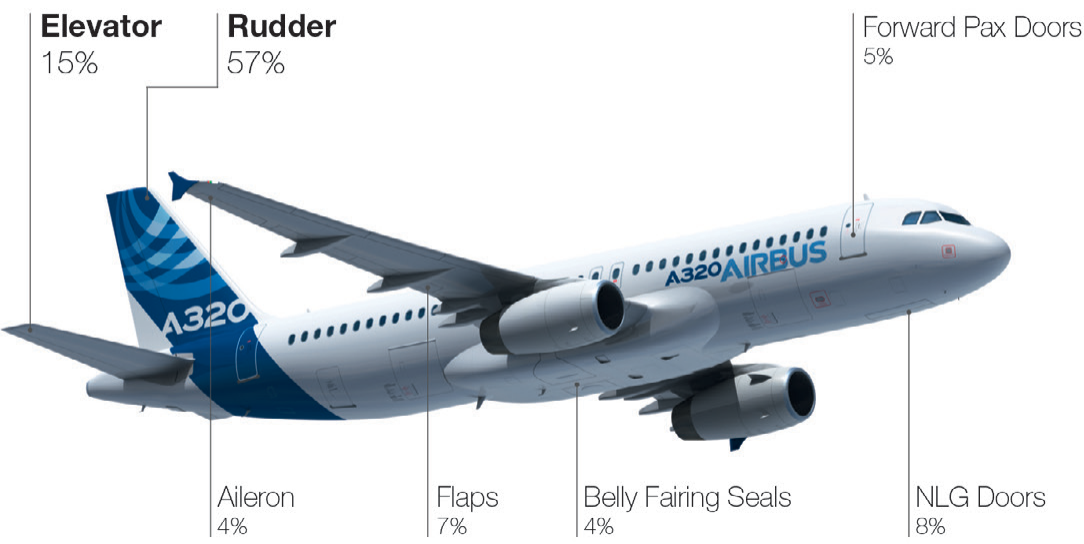
Section titled “Causes of vibration”Due to the size of the fleet, the majority of reports of airframe vibrations on Airbus aircraft are received on A320 Family models. To identify the causes of vibration, Airbus organised a four year working group with airlines and equipment manufacturers, which focussed on the A320 Family fleet. This work identified that the majority of vibrations arise in the aircraft tail section, including 57% of vibrations from the rudder, and 15% from the elevator. Moveable control surfaces in the wings together account for only 11%, whereas sources in belly fairings, passenger and landing gear doors account for 17%.
(fig.1)
Section titled “(fig.1)”Main sources of vibration on A320 Family aircraft, identified by the Airframe Vibration working group
Limited Cycle Oscillations do not create any handling or performance concern.
The main contributor to vibrations, particularly on flight control surfaces, is free-play of servo-control bearings, servo-control attachments, and and/or surface hinge lines (bearings & attachment). Free-play is primarily caused by wear.
When free-play is present, the flight control surface or door will have a tendency to oscillate slightly within the space created by the free-play whenever the surface is at zero hinge-moment. When in this condition, an observable vibration will only start if an energy input is provided, typically from aerodynamic effects of a sufficiently high air speed. This phenomenon is called a ‘Limited Cycle Oscillation’ (LCO).
Limited Cycle Oscillations (LCO) and Safety
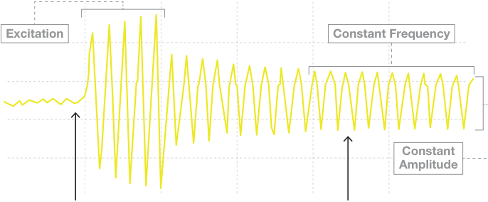
Section titled “Limited Cycle Oscillations (LCO) and Safety”LCO are characterised by a stable and non-divergent vibration of constant amplitude and frequency, after initiation by the triggering input. LCO do not create any handling or performance concern, since surfaces and systems remain fully efficient during the vibration. It is a stable self-sustained non-diverging phenomenon.
An LCO vibration cannot diverge into flutter because whenever the LCO amplitude increases, the damping term involved in LCO mechanics also increases and leads automatically to a decrease of amplitude. The extra damping comes from the increased stiffness caused by the increased amplitude on the involved free-play area; the force of components pushing against each other.
(fig.2)
Section titled “(fig.2)”Waveform of a Limited Cycle Oscillation (LCO).
An LCO vibration cannot diverge into a flutter phenomenon because any increase in vibration amplitude is damped by the force of components pushing against each other.
Since airframe vibrations only occur during flight, maintenance personnel will need pilots to make observations of the vibration.
Excitation
Section titled “Excitation”LCO vibration remains limited at same frequency & amplitude. Structural damping prevents divergence to flutter
Energy such as sufficient airspeed is needed in order to excite a vibration
Reporting to maintenance personnel
Section titled “Reporting to maintenance personnel”Upon experiencing an airframe vibration, quick action is recommended in order to identify and resolve the cause of the vibration. It is therefore important that flight crew report the vibration to their maintenance personnel.
Maintenance personnel are provided with appropriate procedures in the TroubleShooting Manuals (TSM) for resolving the issue. However, since airframe vibrations only occur during flight, maintenance personnel will need pilots to make observations of the vibration.
The Vibration Reporting Sheet (VRS)
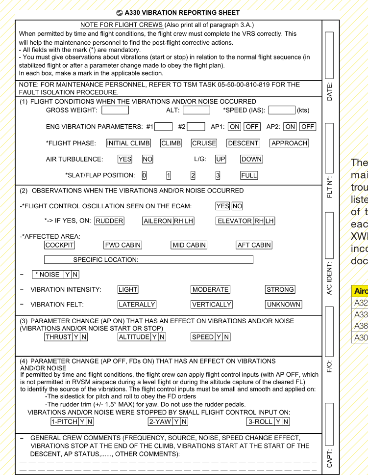
Section titled “The Vibration Reporting Sheet (VRS)”To collect pilot observations, a ‘Vibration Reporting Sheet’ (VRS) is provided within the TSM procedure ‘Identifi cation of the cause of In-Flight Airframe Vibrations and/ or Noises’. A well completed VRS will provide suffi cient information to maintenance crew to help them complete a Decision Tree and Decision Table, so that they can identify the specifi c part of the aircraft which is vibrating.
As can be seen in (fi g.3) , the VRS is split into four sections as follows:
1. Flight conditions when the vibrations and/or noise occur
2. Observations when the vibrations and/or noise occur
3. Parameter changes with AP ON that have an effect on vibration
If a control input is made and the vibration stops, knowing which control surfaces have been commanded helps identify the source of the vibration.
4. Parameter changes with AP OFF that have an effect on vibration
Section 1 of the VRS collects basic fl ight information. Sections 2 to 3 include further data collection fi elds which do not require pilots to make any specifi c control inputs.
(fi g.3)
Section titled “(fi g.3)”The Vibration Reporting Sheet (VRS)
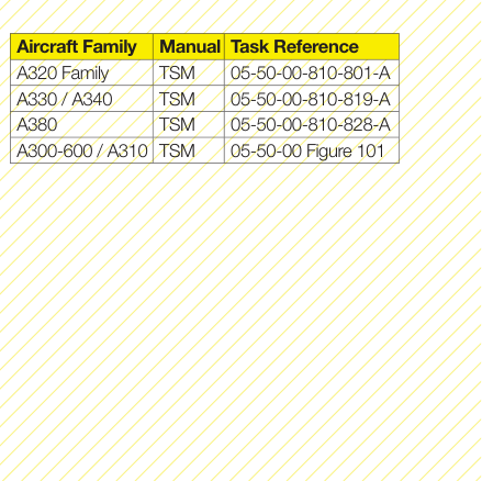
The VRS is found within the relevant maintenance documentation for troubleshooting airframe vibrations, as listed in the table below. The contents of the VRS are almost identical for each Airbus aircraft model. A350 XWB documentation is planned to be incorporated into Line Maintenance documentation by Q1 2018.
The information needed in Section 3 of the VRS can be collected with the autopilot ON, whereas Section 4 requires the autopilot to be OFF.
The information needed in section 2 can be found when the vibration occurs, by observation of the aircraft, its instruments, and the vibration. Corroboration of flight crew with cabin crew observations of where the vibration is the strongest is recommended for a higher reliability of the reported information.
Vibrations can be caused when a control surface is in the zero hinge-moment position. Therefore, the principle for the information collected in sections 3 and 4 is to monitor the vibration when a control input is made and a control surface is moved out of the zero hinge-moment position. If a control input is made and the vibration changes, this gives a useful indication of the surface involved in the vibration.
However, there is an important difference between the pilot actions necessary for section 3 and the actions necessary for section 4.
The information needed in section 3 of the VRS can be collected by observing the aircraft with the autopilot ON, whereas the information in section 4 of the VRS can only be collected with the autopilot OFF. The goal is to observe any change in the vibration, including whether it becomes weaker or stops, or becomes stronger.
In section 3, observations are made whenever the autopilot itself commands a change in thrust setting, turn, climb or descent. The only manual action listed in this section of the VRS is selection of the speed brakes by a few degrees. A change of the vibration due to speed brake extension can indicate that the vibration originates in the elevator.
Either elevator or rudder would be implicated as the source of vibration if a change in the vibration results from a change in altitude setting or in thrust setting. Ailerons would be the principle structural element impacted if the vibration is changed during a turn.
Section 4 of the VRS is only intended to be used if sections 2 and 3 do not succeed in helping identify the source of the vibration. Observations of the vibration are made when the pilot flying directly makes small and smooth flight control inputs, using the side-stick for pitch and roll inputs, or the rudder trim for yaw inputs.
A change in the vibration due to a pitch input indicates that the elevator is the most likely source of vibration. A change in the vibration due to a yaw input indicates the rudder is the most likely source of vibration. And finally, a change in the vibration due to a roll input primarily indicates that the vibration comes from the ailerons.


THE VRS IN PRACTICE
Section titled “THE VRS IN PRACTICE”RVSM airspace
Section titled “RVSM airspace”Today, the vast majority of commercial aviation operations takes place within Reduced Vertical Separation Minima (RVSM) airspace. A regulated requirement of conducting operations in RVSM airspace is to maintain an Auto Pilot (AP) engaged in order to ensure that the aircraft does not deviate from its assigned altitude.
Sections 1 to 3 of the VRS can all be completed with the AP ON. However, section 4 can only be completed with the AP OFF, and therefore cannot be performed in RVSM airspace. This condition means that completing section 4 of the VRS may not always be appropriate in all airline operations.
Airline policy
Section titled “Airline policy”Although flying with AP OFF is a normal task for pilots, some operators prefer to have only technical pilots complete section 4 of the VRS because it may involve non-routine manoeuvres. Some operators prefer to conduct VRS evaluations on a non-revenue flight.
Section 4 of the VRS can only be completed with the AP OFF, and therefore cannot be performed in RVSM airspace.
In whichever way an operator chooses to complete section 4 of the VRS, the associated instructions in the TSM clarify the appropriate technique for implementing the procedure. This includes the following points:
Appropriate technique for applying section 4
Section titled “Appropriate technique for applying section 4”-
When permitted by flight conditions and airline policy, and when not in RVSM airspace, the flight crew can disconnect the Auto Pilot to try to identify the source of the vibrations
-
All inputs must be smooth and follow the Flight Director (FD) bar guidance
-
Usually only very small inputs are sufficient to stop the vibration
-
Large control inputs are neither required nor recommended for the purpose of VRS evaluation, especially when flying with passengers on-board
-
Apply the procedure in the sequence pitch, roll and then yaw
-
If vibrations do not stop, apply small rudder trim inputs of +/- 1.5° MAX (yaw)
-
Do not use rudder pedals
-
When the reporting is completed, AP should be set back on again as required
CONTRIBUTORS:
Section titled “CONTRIBUTORS:”Capt. Christian NORDEN Director Flight Operations & Training Policy
Jean-François BOURCHANIN
Section titled “Jean-François BOURCHANIN”Flight control systems expert, Customer Services
Nicolas SEYNAEVE Stabilizers Product Leader Senior Structure Engineer Structure Engineering Support Customer Services
Florence DOYEN Operational and Training Policy
Christophe LE-GARREC Aeroelastics Engineer
In-flight aircraft vibrations can sometimes be experienced, leading to passenger discomfort. The vibrations are caused generally caused by wear of components.
These vibrations do not create any handling or performance concern, and cannot diverge into flutter since they are damped by the surrounding structure and systems. However, to prevent further degradation of equipment, they should be resolved quickly.
To help identify the source of the vibration, observations must be made during flight. Maintenance personnel provide the flight crew with a Vibration Reporting Sheet (VRS), which structures flight crew observations of the vibration into a useful form for maintenance personnel.
Sections 1 to 3 of the VRS can be completed by pilot observation only, without any need for specific action. If sections 1 to 3 of the VRS do not allow to identify the source of the vibration, it becomes necessary to apply section 4.
Section 4 of the VRS can only be performed with Auto Pilot OFF, and therefore cannot be completed in RVSM airspace. An appropriate technique has to be applied for these evaluations. Some airlines prefer to have the section 4 procedures completed by technical pilots on a non-revenue flight.
Further reading
Section titled “Further reading”|---|---|---|---| ||||| |ISI|A320 Family|27.34.00002|Elevator vibrationsprevention| |ISI|A320 Family|27.24.00001|Prevention of the rudder vibration| |FOT|A320 Family|999.0084/11|In fight vibrations reporting| |FOT|A380|999.0004/14|In fight vibration and noise reporting|
Safety fi rst
Section titled “Safety fi rst”Safety fi rst, #24 August, 2017. Safety fi rst is published by Airbus S.A.S. - 1, rond point Maurice Bellonte - 31707 Blagnac Cedex/France. Publisher and Editor: Yannick Malinge, Chief Product Safety Offi cer. Concept Design by Airbus Multi Media Support 20171210. Reference: X00D16031905 Issue 24. Photos by Airbus, Lindner Fotografi e, S. Ramadier, H. Goussé, P. Masclet, F. Lancelot, A, Doumenjou, J. V. Reymondon, A. Tchaikovsky, C. Sadonnet, P. Pigeyre, A. Balazh. Computer renderings by Fixion.
机身振动故障排除
Section titled “机身振动故障排除”来源:Airbus Safety First 网址:https://safetyfirst.airbus.com/troubleshooting-airframe-vibrations/ 发布日期:2017-07-29 杂志期号:2017-08 类别:飞行运营、维护、报告、故障排除、振动、VRS PDF:原始 PDF
随着可动结构部件(如操纵面和起落架舱门)的老化,铰链和作动器的磨损有时会导致机身振动。这些振动可能在客舱内产生噪音并造成身体不适。
为防止部件进一步恶化,应快速识别并消除振动原因。为此,维护人员需要飞行机组使用振动报告单(VRS)对振动进行观察记录。
在进行观察之前,清晰了解如何填写 VRS 非常重要。VRS 的某些部分需要关闭自动驾驶仪进行手动控制输入,因此无法在 RVSM 空域内执行。
飞行中的机身振动
Section titled “飞行中的机身振动”如今,空客机队受益于多年积累的运营经验,飞行中机身振动的报告相对较少。然而,机身振动仍时有报告。
当发生机身振动时,机上人员可以察觉到。根据振动来源的不同,可能表现为物理移动、或噪音、或移动和噪音兼有。这些体验可能导致乘客担忧和不适。此外,任何振动都意味着部件磨损加剧。鉴于上述原因,应迅速确定振动原因。
机上体验到的振动可能导致乘客担忧和不适。
由于机队规模的原因,空客飞机的大多数机身振动报告来自 A320 系列机型。为识别振动原因,空客与航空公司及设备制造商组织了一个为期四年的工作组,重点关注 A320 系列机队。这项工作确定,大多数振动发生在飞机尾部区域,其中 57% 来自方向舵,15% 来自升降舵。机翼上的可动操纵面合计仅占 11%,而机身腹部整流罩、客舱门和起落架舱门占 17%。
A320 系列飞机振动主要来源,由机身振动工作组确认
有限循环振荡不会产生任何操纵或性能方面的问题。
振动的主要来源,特别是对于飞行操纵面,是伺服控制轴承、伺服控制连接和/或表面铰链线(轴承和连接件)的间隙。间隙主要由磨损引起。
当存在间隙时,飞行操纵面或舱门在铰链力矩为零时会倾向于在间隙产生的空间中轻微振荡。在这种情况下,只有提供能量输入(通常来自足够高空速的气动效应)时才会开始出现可观察到的振动。这种现象称为”有限循环振荡”(LCO)。
有限循环振荡(LCO)与安全
Section titled “有限循环振荡(LCO)与安全”LCO 的特征是,在触发输入启动后,振动幅度和频率保持稳定且不发散。由于在振动过程中操纵面和系统保持完全有效,LCO 不会产生任何操纵或性能方面的问题。这是一种稳定的、自持的、非发散的现象。
LCO 振动不会发散为颤振,因为每当 LCO 振幅增加时,LCO 力学中涉及的阻尼项也会增加,并自动导致振幅减小。额外的阻尼来自间隙区域因振幅增加而产生的刚度增大;即部件相互推压的力。
有限循环振荡(LCO)的波形。
LCO 振动不会发散为颤振现象,因为任何振幅的增加都会被部件相互推压的力所阻尼。
由于机身振动仅在飞行中发生,维护人员需要飞行员对振动进行观察。
LCO 振动保持在相同的频率和振幅。结构阻尼防止发散为颤振
需要能量(如足够的气流速度)才能激发振动
向维修人员报告
Section titled “向维修人员报告”遭遇机体振动时,建议迅速采取行动,以识别和解决振动原因。因此,飞行机组向维修人员报告振动情况至关重要。
维修人员可从排故手册(TSM)中获得解决此类问题的相应程序。然而,由于机体振动仅在飞行中出现,维修人员需要飞行员对振动进行观察。
振动报告单(VRS)
Section titled “振动报告单(VRS)”为收集飞行员观察信息,排故手册程序“飞行中机体振动和/或噪音原因识别”中提供了“振动报告单”(VRS)。填写完整的VRS将为维修人员提供足够的信息,以帮助其完成决策树和决策表,从而识别发生振动的具体部件。
如图(fi g.3)所示,VRS分为以下四个部分:
1. 振动和/或噪音发生时的飞行条件
2. 振动和/或噪音发生时的观察结果
3. 自动驾驶接通时对振动产生影响的参数变化
若进行控制输入后振动停止,则了解所偏动的操纵面有助于识别振动来源。
4. 自动驾驶断开时对振动产生影响的参数变化
VRS第1部分收集基本飞行信息。第2至3部分包含进一步的数据收集字段,无需飞行员进行任何特定的控制输入。
(fi g.3)
Section titled “(fi g.3)”振动报告单(VRS)
VRS位于相关维护文档中,用于排故机体振动,如下表所列。各空客机型VRS的内容几乎相同。A350 XWB文档计划于2018年第一季度纳入航线维护文档。
VRS第3部分所需信息可在自动驾驶接通时收集,而第4部分则需要自动驾驶断开。
第2部分所需信息可在振动发生时通过对飞机本身、仪表及振动的观察获得。建议飞行机组与客舱机组相互印证振动最强烈的位置,以提高报告信息的可靠性。
当操纵面处于零铰链力矩位置时可能产生振动。因此,第3和第4部分收集信息的原则是:当进行控制输入并使操纵面偏离零铰链力矩位置时,监测振动情况。若进行控制输入后振动发生变化,可有效指示参与振动的部件。
然而,第3部分与第4部分所需的飞行员动作存在重要差异。
VRS第3部分所需信息可通过在自动驾驶接通状态下观察飞机来收集,而VRS第4部分所需信息只能在自动驾驶断开时收集。目的是观察振动的任何变化,包括振动是否变弱或停止,或是否变强。
在第3部分中,当自动驾驶本身指令推力设置、转弯、爬升或下降发生变化时进行观察。该部分VRS中列出的唯一手动操作是将减速板放出几度。振动因减速板伸出而产生的变化可表明振动源自升降舵。
若振动因高度设置或推力设置的变化而发生变化,则升降舵或方向舵均可能为振动来源。若振动在转弯过程中发生变化,则副翼为主要受影响结构件。
VRS第4部分仅在第2和第3部分未能成功识别振动来源时使用。在飞行员直接进行小幅度、平滑的飞行控制输入时观察振动,使用侧杆进行俯仰和滚转输入,或使用方向舵配平进行偏航输入。
振动因俯仰输入而发生变化,表明升降舵是最可能的振动来源。振动因偏航输入而发生变化,表明方向舵是最可能的振动来源。振动因滚转输入而发生变化,则主要表明振动来自副翼。
实际应用中的 VRS
Section titled “实际应用中的 VRS”RVSM 空域
Section titled “RVSM 空域”如今,绝大多数商业航空运营活动在缩小垂直最小间隔 (RVSM) 空域内进行。在 RVSM 空域内实施运营的一项规定要求是保持自动驾驶 (AP) 接通,以确保飞机不偏离指定高度。
VRS 的第 1 至 3 部分均可在 AP 接通状态下完成。但第 4 部分只能在 AP 断开时完成,因此无法在 RVSM 空域内执行。此条件意味着完成 VRS 第 4 部分可能并非在所有航空公司运营中均适用。
航空公司政策
Section titled “航空公司政策”虽然自动驾驶断开飞行对飞行员而言是一项正常任务,但部分运营商倾向于仅由技术飞行员完成 VRS 第 4 部分,因为其中可能涉及非例行机动。有些运营商倾向于在非商业航班上进行 VRS 评估。
VRS 第 4 部分只能在 AP 断开时完成,因此无法在 RVSM 空域内执行。
无论运营商选择以何种方式完成 VRS 第 4 部分,TSM 中的相关说明均阐明了实施该程序的适当技术。其中包括以下要点:
实施第 4 部分的适当技术
Section titled “实施第 4 部分的适当技术”-
在飞行条件允许且符合航空公司政策、且不在 RVSM 空域时,飞行机组可断开自动驾驶以尝试识别振动源
-
所有输入必须平滑并遵循飞行指引仪 (FD) 杆引导
-
通常仅需非常小的输入即可制止振动
-
大幅度控制输入既非必须亦非推荐用于 VRS 评估目的,尤其是在机上载有乘客时
-
按俯仰、横滚然后偏航的顺序应用程序
-
如果振动未停止,应用不超过 +/- 1.5° 的小方向舵配平输入(偏航)
-
请勿使用方向舵脚蹬
-
报告完成后,按需重新接通自动驾驶
Capt. Christian NORDEN 飞行运营与培训政策总监
Jean-François BOURCHANIN
Section titled “Jean-François BOURCHANIN”飞控系统专家,客户服务部
Nicolas SEYNAEVE 水平安定面产品负责人 高级结构工程师 结构工程支持 客户服务部
Florence DOYEN 运营与培训政策
Christophe LE-GARREC 气动弹性工程师
飞行中的飞机振动有时会被感受到,导致乘客不适。振动通常由部件磨损引起。
这些振动不会产生任何操纵或性能方面的问题,且不会发散成颤振,因为它们被周围结构和系统所阻尼。然而,为防止设备进一步恶化,应尽快予以解决。
为帮助识别振动源,必须在飞行期间进行观察。维修人员向飞行机组提供振动报告单 (VRS),将飞行机组对振动的观察整理成对维修人员有用的形式。
VRS 的第 1 至 3 部分可仅通过飞行员观察完成,无需采取任何特定行动。如果 VRS 的第 1 至 3 部分无法识别振动源,则有必要执行第 4 部分。
VRS 第 4 部分只能在自动驾驶断开时执行,因此无法在 RVSM 空域内完成。进行这些评估时必须采用适当的技术。部分航空公司倾向于让技术飞行员在非商业航班上完成第 4 部分程序。
|---|---|---|---| ||||| |ISI|A320 系列|27.34.00002|升降舵振动预防| |ISI|A320 系列|27.24.00001|方向舵振动预防| |FOT|A320 系列|999.0084/11|飞行中振动报告| |FOT|A380|999.0004/14|飞行中振动和噪音报告|
Safety first
Section titled “Safety first”Safety first, #24 2017 年 8 月。Safety first 由空中客车公司出版 - 1, rond point Maurice Bellonte - 31707 Blagnac Cedex/法国。出版人与编辑:Yannick Malinge,首席产品安全官。概念设计由空中客车多媒体支持 20171210。参考编号:X00D16031905 第 24 期。照片由空中客车、Lindner Fotografie、S. Ramadier、H. Goussé、P. Masclet、F. Lancelot、A. Doumenjou、J. V. Reymondon、A. Tchaikovsky、C. Sadonnet、P. Pigeyre、A. Balazh 提供。计算机渲染由 Fixion 完成。