A Focus on the Takeoff Rotation
Source: Airbus Safety First URL: https://safetyfirst.airbus.com/a-focus-on-the-takeoff-rotation/ Published: 2021-01-18 Category: Flight Ops, overrun, pitch, PTM, rotation, runway, runway excursion, runway overrun, tailstrike, take off, TSI, Vr PDF: Original PDF

An appropriate takeoff rotation maneuver is a balance between good takeoff performance and sufficient margin versus tail strike, stall speed, and minimum control speeds.
Applying the 3°/s rotation rate requested in the SOPs is the key to ensure that the aircraft meets the expected takeoff performance. Flight data monitoring shows that the rotation rate values in service and a lower rotation rate vary observed in some cases with the associated degradation takeoff performance. This article describes both the takeoff rotation laws available on Airbus Fly-by-Wire (FBW) aircraft and the recommended rotation techniques that will enable flight crew to achieve consistent takeoff rotations at the requested rotation rate.
This article is also available on safetyfirst.airbus.com and on the Safety first app for iOS and Android devices.
CASE STUDY: A340 LONG TAKEOFF
Section titled “CASE STUDY: A340 LONG TAKEOFF”Event Description
Section titled “Event Description”A takeoff from a high altitude airport (8360 ft)
Section titled “A takeoff from a high altitude airport (8360 ft)”An A340-300 was performing a takeoff from a high altitude airport. A TOGA thrust takeoff in CONF2 was selected. The takeoff performance was calculated for a 4 kt tailwind and was limited by the runway length (takeoff run in One Engine Inoperative (OEI) condition). The gross weight of the aircraft was 236.9 t and was close to the Maximum Takeoff Weight of 237 t in the conditions of the day.
An uneventful takeoff roll
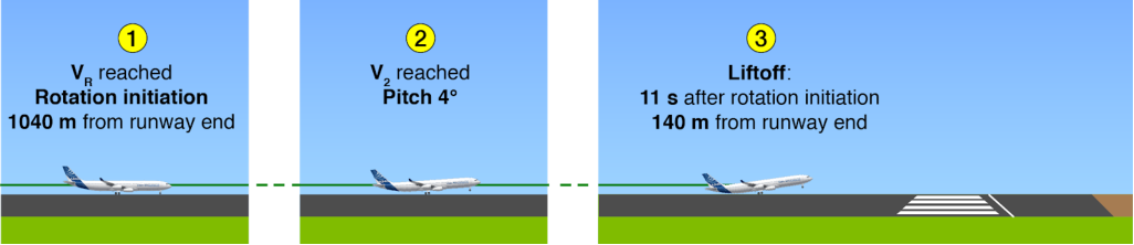
Section titled “An uneventful takeoff roll”The aircraft reached V1 (128 kt) 54 s after brake release and TOGA thrust application. The Pilot Flying (PF) then initiated the rotation close to VR. The nose landing gear lifted off the ground 1 s later and the pitch began to increase.
A late liftoff
Section titled “A late liftoff”V2 (149 kt) was reached with the aircraft still on the ground. The main landing gear was still compressed and the aircraft had a pitch of 4° up. Liftoff occurred 11 s after rotation initiation at 155 kt, and at only 140 m from the runway end with a recorded pitch of 9° up.
(fig.1) Sequence of events from VR to liftoff
Runway end overflown at 6 ft radio altitude
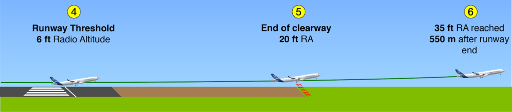
Section titled “Runway end overflown at 6 ft radio altitude”The aircraft flew over the runway end at 6 ft Radio Altitude (RA), and then overflew the end of the clearway at 20 ft RA and avoided the LOC antennas only 12 ft. The aircraft eventually reached 35 ft RA 550 m after the runway end. The landing gear was selected up 3 s later at 135 ft RA with a vertical speed 1300 ft/min, pitch at 12°, and speed at 160 kt. The aircraft continued its climb and completed its flight uneventfully.
Despite what seemed to be a standard takeoff roll, the aircraft lifted off the runway very late, overflying the LOC antennas located at the end of the clearway with very little clearance. How did this happen?
(fig.2) Sequence of events from runway threshold to 35 ft RA
Event Analysis
Section titled “Event Analysis”A nominal aircraft acceleration performance until VR
The analysis of the DFDR data showed that the aircraft acceleration was accordance with the expected performance in the conditions of the day reported as wet runway with 4 kt tailwind.
A slow rotation rate during takeoff
Section titled “A slow rotation rate during takeoff”The sidestick inputs ordered by the PF during the rotation resulted in an average rotation rate of 1°/sec. Airbus SOPs request a 3°/s rotation rate. This slow rotation rate resulted in degraded takeoff performance leading to a significant increase the takeoff distance.
THE REQUESTED TAKEOFF ROTATION RATE VALUE
Section titled “THE REQUESTED TAKEOFF ROTATION RATE VALUE”The origin of the requested rotation rate
Section titled “The origin of the requested rotation rate”The rotation rate that is used to compute the takeoff performance was determined during the takeoff performance flight test campaign together with the Airworthiness Authorities. This value is the average of the rotation rates recorded during all of the test aircraft takeoffs performed in a variety of operating conditions.
The requested 3°/s rotation rate was the value selected and is applicable to Airbus aircraft except for the A220, which has a 3 to 5°/s rate requested in FCOM. This value ensured that the actual takeoff distance is closest to the computed distance. If the PF applies a rotation rate that is lower than the requested rotation rate, the aircraft may not take off according to the computed performance, leading to an increased takeoff distance and a decreased obstacle clearance.
Rotation rate too low in some takeoffs
Section titled “Rotation rate too low in some takeoffs”“The requested 3°/s rotation rate was the value selected and is applicable to all Airbus aircraft except for the A220, which has a 3 to 5°/s rate requested in its FCOM.”
Flight data monitoring shows that the rotation rate values recorded in service vary. A low rotation rate with an associated takeoff performance degradation was observed in some cases. Safety margins used in takeoff performance computation prevent any significant problems in most cases. However, these margins may not be sufficient in certain situations as can be seen in the event described above. It is why flight crews should always perform the takeoff rotation at a rate as close as possible to the requested rotation rate, and this is especially important conditions where performance is limited by runway length or obstacle clearance.
A significant impact on takeoff performance
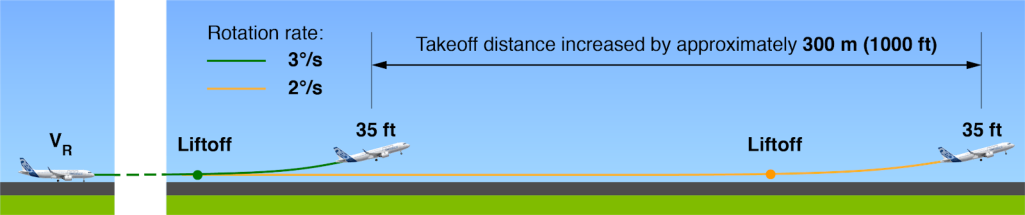
Section titled “A significant impact on takeoff performance”A rotation rate lower than the requested 3°/s in the SOPs significantly increases the takeoff distance. For example, a takeoff performed with a 2°/s rotation rate increases the takeoff distance by approximately 300 m (1000 ft) compared to 3°/s rotation rate.
(fig.3) Impact of a lower rotation rate on the takeoff distance
Takeoff Distance (TOD) margins
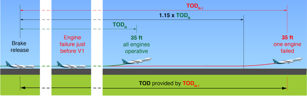
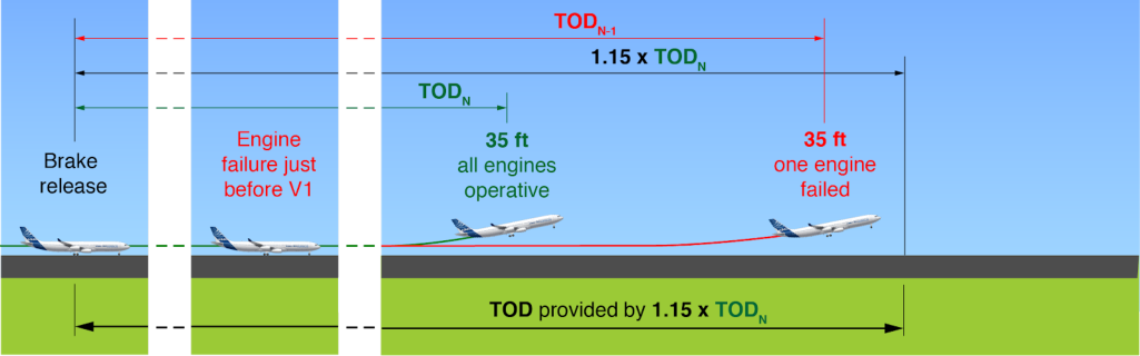
Section titled “Takeoff Distance (TOD) margins”The regulatory Takeoff Distance ( TOD ) on a dry runway is calculated by taking the greatest value of:
-
the TOD computed with one engine failure happening just prior to reaching V1 ( TODN-1 ), or
-
the TOD computed with all engines operative ( TODN ) with an additional margin of 15 %.
TODdry = max of { TODN-1 ; 1.15 x TODN }
Section titled “TODdry = max of { TODN-1 ; 1.15 x TODN }”Twin-engine aircraft
Section titled “Twin-engine aircraft”On a twin-engine aircraft, the TOD is often provided by the TODN-1 because the loss of half of its thrust strongly impacts the takeoff distance. This calculation provides additional margin for a takeoff with both engines operative.
While the PF should perform the requested rotation rate of 3°/s in all conditions, it (fig.4) Example of a TOD is even more important in case of engine failure during takeoff, because there is computation for a no additional margin for the calculated TOD. twin-engine aircraft
Four-engine aircraft
Section titled “Four-engine aircraft”On a four-engine aircraft, the TOD is often sized by the factored TODN because the TODN-1 is often the shortest as it is computed with a loss of thrust limited to a quarter of the total available thrust.
Achieving the requested rotation rate of 3°/s is especially important in daily operations (i.e. when all four engines are operative), because this condition usually the sizing one, and therefore, does not provide additional margin on top of the 1.15 factor.
(fig.5) Example of a TOD computation for a twin-engine aircraft
TAKEOFF ROTATION LAWS AVAILABLE ON FBW AIRCRAFT
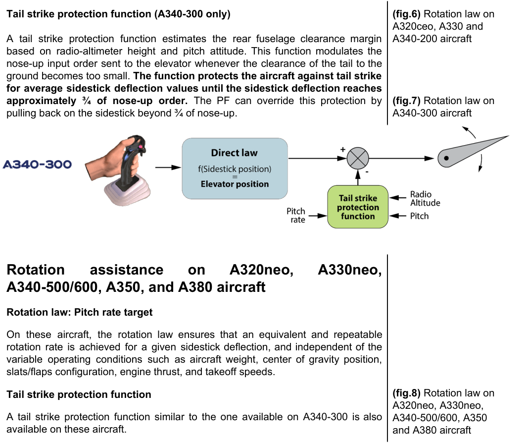
Section titled “TAKEOFF ROTATION LAWS AVAILABLE ON FBW AIRCRAFT”The takeoff rotation law helps the flight crew to perform the optimum takeoff rotation. The takeoff rotation law consists of both the rotation law and tail strike prevention functions.
There are different types of takeoff rotation law depending on the aircraft model.
Rotation assistance on A320ceo, A330ceo, and A340-200/300 aircraft
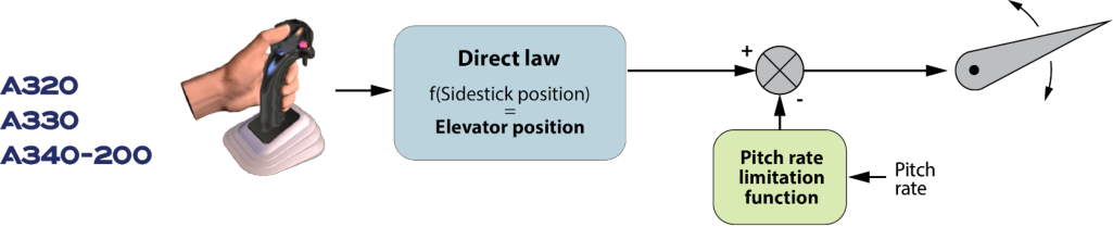
Section titled “Rotation assistance on A320ceo, A330ceo, and A340-200/300 aircraft”Rotation law: Direct law
Section titled “Rotation law: Direct law”There is a direct relationship between the sidestick deflection and the elevator deflection on these aircraft models. The rotation rate obtained by a fixed sidestick deflection value may vary noticeably with different operating conditions such as aircraft weight, center of gravity position, slats/flaps configuration, engine thrust, and takeoff speeds.
Tail strike prevention: Pitch rate limitation function (A320ceo, A330ceo, A340-200)
A limitation function reduces the pitch-up command sent to the elevators to reduce the risk of tail strike in case of excessive pitch rate. This pitch rate limitation function does not provide tail strike protection : If a nose-up input is maintained on the sidestick, a tail strike can still occur.
Tail strike pitch limit indication at takeoff (A330/A340 family and A380 aircraft)
Section titled “Tail strike pitch limit indication at takeoff (A330/A340 family and A380 aircraft)”The tail strike pitch limit indication is currently displayed at takeoff and landing on all A340 and A380 aircraft. The tail strike pitch limit was an option on the earlier models of the A330ceo, but was later installed as standard for all A330ceo produced after mid-2013.
A320, A321, A330neo, and A350 aircraft also have a tail strike pitch limit, but it is only displayed on landing, because it is not necessary at takeoff. There is no tail strike pitch limit indication on A318 and A319 aircraft, because these aircraft have shorter length fuselage and less risk of tail strike. Removing the tail strike pitch limit for takeoff
(fig.9) Example of a tail strike pitch limit indication on an A330 aircraft
In-service experience showed that when the tail strike pitch limit indicator appears on the display, it may cause the PF to unnecessarily reduce the rotation rate the aircraft during takeoff and prevent the aircraft from reaching the requested 3°/s rotation rate. As a result, Airbus decided to deactivate the tail strike pitch limit indicator at takeoff and to keep it activated only on landing for all aircraft models. The tail strike protection function proved to provide A340-300, A340-500/600, and A380 aircraft with sufficient tail strike protection. The pitch rate limitation function on A330ceo aircraft, combined with its tail strike margin is sufficient protection against the risk of tail strike. Deactivation of the tail strike pitch limit indication for takeoff will be performed the opportunity of a next A330/A340 Flight Management Guidance and Enveloppe Computer (FMGEC) or A380 Flight Control and Guidance Computer (FCGC) update.
Rotation assistance on A220 aircraft Rotation law: Direct law There is a direct relationship between the sidestick deflection and elevator deflection with a compensation for forward or aft center of gravity conditions on (fig.10) Pitch Target A220 aircraft. Marker (PTM) on the PFD of an A220 Pitch Target Marker (PTM) aircraft The Pitch Target Marker (PTM) on the PFD provides the initial pitch for the flight crew to target during the takeoff rotation until FD guidance is available. Tail strike prevention: Pitch rate reduction A limitation function will reduce the pitch-up command sent to the elevators in case of excessive pitch rate, and will reduce the risk of tail strike. The flight crew should be aware that this pitch rate limitation is not protection against tail strike : A tail strike event can still occur if a nose-up input is maintained on the sidestick. A tail strike symbol is displayed on the Head-Up Display (HUD) during rotation when the PTM is not displayed and the aircraft pitch angle approaches the tail strike angle by less than 3 degrees or when the pitch rate is excessive.
THE TAKEOFF ROTATION TECHNIQUE
Section titled “THE TAKEOFF ROTATION TECHNIQUE”A technique common to all FBW and non-FBW aircraft
Section titled “A technique common to all FBW and non-FBW aircraft”A similar technique is used on all Airbus aircraft. It can be found in the FCOM SOPs, and additional information is provided in the Flight Crew Techniques Manual (FCTM).
Step 1: Initiate Rotation
Section titled “Step 1: Initiate Rotation”When the aircraft reaches VR , the PF should apply a positive backward sidestick (or control column) input to initiate the rotation.
“A similar technique is used on all Airbus aircraft”
Step 2: Use outside visual references to achieve & maintain rotation rate
Section titled “Step 2: Use outside visual references to achieve & maintain rotation rate”After the PF initiates the rotation, they should use outside visual references to achieve and maintain the rotation rate.
Adjustments may be necessary to achieve and maintain the required rotation rate. On aircraft with direct rotation law or non-FBW aircraft, the flight crew should adapt to the takeoff conditions on the day. On aircraft that have the pitch rate rotation law, the law assists the flight crew to achieve an equivalent rotation in all conditions.
With a suitable rotation rate, the aircraft typically lifts off approximately 4 to 5 after the PF initiates the rotation and when the pitch reaches approximately 10°.
Step 3: Target initial pitch attitude after liftoff then follow FD guidance
Section titled “Step 3: Target initial pitch attitude after liftoff then follow FD guidance”When the aircraft is airborne, the PF should adjust the pitch toward the initial pitch target provided in the FCOM (e.g. 15° or 12.5° if one engine failed on A320 aircraft). On A220 aircraft, the Pitch Target Marker (PTM) provides a visual indication of the initial target pitch. The PF should then follow the FD guidance.
(fig.11) Recommended rotation technique
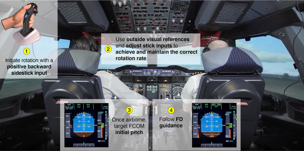
The “What about rotation technique?” video is available on the Worldwide Instructor News (WIN) website and provides step-by-step review of a full takeoff sequence performed in an A380 simulator.
Training Areas of Special Emphasis (TASE) for A340 family aircraft
Section titled “Training Areas of Special Emphasis (TASE) for A340 family aircraft”An EASA Safety Information Bulletin (SIB 2017/20) was published in 2017 following the incident described in this article. In 2018, a Training Areas Special Emphasis (TASE) was included in the A340 Operational Suitability Data (OSD) for flight crew in response to the SIB. The TASE emphasizes the need to ensure flight crews know how to perform the correct takeoff rotation technique during initial and recurrent training. This includes:
-
How to initiate the rotation
-
How to achieve and maintain the rotation rate
-
How to achieve the pitch attitude after liftoff.
Contributors:
Section titled “Contributors:”Sebastien BALZER Aircraft Performance Engineer Design Office
Philippe CASTAIGNS Experimental Test pilot Flight Tests
Stéphane DELANNOY Aircraft Stability & Control Engineer Design Office
Thomas LEPAGNOT Accident/Incident investigator Product Safety
Xavier LESCEU A220 Chief Pilot Test Pilot - TRI/TRE Customer Services
Flight data monitoring shows that the takeoff rotation rates recorded in service vary and that a lower rotation rate is observed in some cases, with the associated degradation of takeoff performance.
Achieving an appropriate rotation rate is essential to ensure takeoff performance, while maintaining a sufficient margin with tail strike, stall speed, and minimum control speeds.
Airbus aircraft are designed, tested, and certified to achieve the necessary rotation rate, while having sufficient margins against the tail strike. Flight control laws include features that reduce the risk tail strike.
The flight crew should apply the FCOM procedures and FCTM techniques to achieve the requested rotation rate:
After the rotation is initiated with a positive nose-up input, the flight crew should use outside visual references to achieve and maintain the rotation. The flight crew should fly the rotation, and make any necessary adjustments to achieve and maintain the required rotation rate. When the aircraft is airborne, the PF adjusts the pitch toward the initial FCOM pitch target and then follows the FD guidance.
Daniel LOPEZ-FERNANDEZ Director Product Safety Enhancement Product Safety
Patrick SALLIER Aircraft Performance Senior Expert Design Office
Gilbert SAVARY
Section titled “Gilbert SAVARY”Head of Operational & Training Policy Flight Operations & Training Support
Safety first , 2021. Safety first is published by Airbus S.A.S. 1, rond point Maurice Bellonte - 31707 Blagnac Cedex/France.
Editor: Yannick Malinge, Chief Product Safety Officer.
Editorial team: Guillaume Estragnat, Vanessa Sadi, Gwyneth Duggan, Tim Roach.
- Reference: X00D16031905.
Photos by Airbus.
© Airbus S.A.S. 2021 – All rights reserved. Proprietary documents.
Section titled “© Airbus S.A.S. 2021 – All rights reserved. Proprietary documents.”关于起飞抬轮的探讨
Section titled “关于起飞抬轮的探讨”
恰当的起飞抬轮动作是在良好的起飞性能与足够的尾触裕度、失速速度和最低控制速度之间取得的平衡。
按照标准操作程序(SOPs)的要求采用 3°/秒 的抬轮率是确保飞机达到预期起飞性能的关键。飞行数据监控表明,实际运营中的抬轮率值以及在某些情况下观察到的较低抬轮率会导致起飞性能下降。本文阐述了空客电传飞控(FBW)飞机上可用的抬轮法则以及建议的抬轮技术,使飞行机组能够以要求的抬轮率完成一致的起飞抬轮动作。
本文也可在 safetyfirst.airbus.com 和适用于 iOS 和 Android 设备的安全第一应用程序中获取。
案例研究:A340 长跑道起飞
Section titled “案例研究:A340 长跑道起飞”高海拔机场起飞(8360 英尺)
Section titled “高海拔机场起飞(8360 英尺)”一架 A340-300 在高海拔机场执行起飞。选择了 TOGA 推力 CONF2 构型起飞。起飞性能按 4 节顺风计算,受跑道长度限制(单发失效条件下的起飞滑行距离)。飞机总重量为 236.9 吨,接近当日条件下的最大起飞重量 237 吨。
平稳的滑跑阶段
Section titled “平稳的滑跑阶段”飞机在松开刹车并施加 TOGA 推力后 54 秒达到 V1(128 节)。然后操纵飞行员(PF)在接近 VR 时开始抬轮。1 秒后前起落架离地,俯仰角开始增大。
当飞机仍在地面时已达到 V2(149 节)。主起落架仍被压缩,飞机俯仰角为 4° 上仰。抬轮开始后 11 秒在 155 节时离地,距离跑道端仅 140 米,记录的俯仰角为 9° 上仰。
(图 1) 从 VR 到离地的事件顺序
以 6 英尺无线电高度飞越跑道端
Section titled “以 6 英尺无线电高度飞越跑道端”飞机以 6 英尺无线电高度(RA)飞越跑道端,随后以 20 英尺无线电高度飞越净空道末端,仅以 12 英尺的余度避开了航向信标(LOC)天线。飞机最终在跑道端后 550 米处达到 35 英尺无线电高度。3 秒后在 135 英尺无线电高度、垂直速度 1300 英尺/分、俯仰角 12°、速度 160 节时选择收起落架。飞机继续上升并顺利完成飞行。
尽管看起来是标准滑跑,飞机却非常晚地离地,飞越位于净空道末端的 LOC 天线时余度极小。这是如何发生的?
(图 2) 从跑道入口到 35 英尺无线电高度的事件顺序
直至 V1 飞机加速性能正常
Section titled “直至 V1 飞机加速性能正常”数字式飞行数据记录仪(DFDR)数据分析表明,飞机加速与当日报告条件(湿跑道、4 节顺风)下的预期性能一致。
起飞抬轮率过慢
Section titled “起飞抬轮率过慢”PF 在抬轮过程中通过侧杆输入的指令产生的平均抬轮率为 1°/秒。空客 SOPs 要求的抬轮率为 3°/秒。这种过慢的抬轮率导致起飞性能下降,使起飞距离显著增加。
要求的起飞抬轮率值
Section titled “要求的起飞抬轮率值”要求抬轮率的来源
Section titled “要求抬轮率的来源”用于计算起飞性能的抬轮率是在与适航当局共同进行的起飞性能飞行测试活动中确定的。该值为所有测试飞机在各种运行条件下执行起飞时记录的抬轮率的平均值。
要求的 3°/秒抬轮率是被选取的值,适用于空客所有飞机,A220 除外(A220 的 FCOM 中要求 3 至 5°/秒)。该值确保实际起飞距离最接近计算距离。如果 PF 施加的抬轮率低于要求的抬轮率,飞机可能无法按照计算性能起飞,导致起飞距离增加和越障裕度降低。
部分起飞中抬轮率过低
Section titled “部分起飞中抬轮率过低”“要求的 3°/秒抬轮率是被选取的值,适用于所有空客飞机,A220 除外(A220 的 FCOM 中要求 3 至 5°/秒)。”
飞行数据监控表明,实际运营中记录的抬轮率值存在差异。在某些情况下观察到低抬轮率伴随着起飞性能下降。起飞性能计算中使用的安全裕度在大多数情况下能够防止任何重大问题。然而,在某些情况下这些裕度可能不够充分,如上述事件所示。这就是为什么飞行机组应始终以尽可能接近要求抬轮率的速率执行起飞抬轮的原因,在受跑道长度或越障限制性能的条件下的情况下尤为重要。
对起飞性能的重大影响
Section titled “对起飞性能的重大影响”SOP中要求的3°/s抬前轮速率若低于此值,会显著增加起飞距离。例如,以2°/s的抬前轮速率执行起飞,相比3°/s的速率,起飞距离约增加300米(1000英尺)。
(图3) 较低抬前轮速率对起飞距离的影响
起飞距离(TOD)裕度
Section titled “起飞距离(TOD)裕度”干跑道上的审定起飞距离(TOD)取以下两者的较大值:
- 起飞时一台发动机失效(恰好在达到V1之前,TODN-1)计算的TOD,或
- 所有发动机工作(TODN)加上15%裕度计算的TOD。
TODdry = max of { TODN-1 ; 1.15 × TODN }
Section titled “TODdry = max of { TODN-1 ; 1.15 × TODN }”在双发飞机上,TOD通常由TODN-1提供,因为失去一半推力会强烈影响起飞距离。该计算为双发工作起飞提供了额外裕度。
虽然PF应在所有条件下执行所要求的3°/s抬前轮速率,但在起飞过程中发生发动机失效时这一点更为重要,因为计算的TOD没有额外裕度。(图4)双发飞机TOD计算示例
在四发飞机上,TOD通常由带系数的TODN决定,因为TODN-1往往是最短的——它是以仅损失四分之一总可用推力计算的。
达到所要求的3°/s抬前轮速率在日常运行中(即四台发动机工作时)尤为重要,因为这种情况下通常是确定尺寸的条件,因此不会在1.15系数的基础上提供额外裕度。
(图5) 双发飞机TOD计算示例
FBW飞机上的起飞抬前轮法则
Section titled “FBW飞机上的起飞抬前轮法则”起飞抬前轮法则帮助飞行机组执行最佳起飞抬前轮。起飞抬前轮法则由抬前轮法则和擦尾预防功能组成。
根据飞机型号的不同,起飞抬前轮法则有不同类型。
A320ceo、A330ceo和A340-200/300飞机的抬前轮辅助
Section titled “A320ceo、A330ceo和A340-200/300飞机的抬前轮辅助”抬前轮法则:直接法则
Section titled “抬前轮法则:直接法则”在这些飞机型号上,侧杆偏转与升降舵偏转之间存在直接关系。固定侧杆偏转值所获得的抬前轮速率会随不同运行条件(如飞机重量、重心位置、缝翼/襟翼构型、发动机推力和起飞速度)而明显变化。
擦尾预防:A320ceo、A330ceo、A340-200的俯仰速率限制功能
限制功能会减小发送至升降舵的抬前量指令,以降低俯仰速率过大时的擦尾风险。此俯仰速率限制功能不提供擦尾保护:如果在侧杆上保持机头向上的输入,仍可能发生擦尾。
起飞时的擦尾俯仰限制指示(A330/A340 系列及 A380 飞机)
Section titled “起飞时的擦尾俯仰限制指示(A330/A340 系列及 A380 飞机)”擦尾俯仰限制指示目前在所有 A340 和 A380 飞机的起飞和着陆时显示。擦尾俯仰限制在早期 A330ceo 型号上是选装项,但后来在 2013 年下半年后生产的所有 A330ceo 上作为标准配置安装。
A320、A321、A330neo 和 A350 飞机也有擦尾俯仰限制,但仅在着陆时显示,因为起飞时不需要。A318 和 A319 飞机上没有擦尾俯仰限制指示,因为这些飞机机身较短,擦尾风险较低。
移除起飞时的擦尾俯仰限制指示
(fig.9) A330 飞机擦尾俯仰限制指示示例
运行经验表明,当擦尾俯仰限制指示器出现在显示器上时,可能导致 PF 在起飞时不必要地降低抬轮速率,从而无法使飞机达到所需的 3°/s 抬轮速率。因此,空客决定在起飞时停用擦尾俯仰限制指示器,仅在着陆时保持激活,适用于所有机型。擦尾保护功能已证明能够为 A340-300、A340-500/600 和 A380 飞机提供充分的擦尾保护。A330ceo 飞机上的俯仰速率限制功能结合其擦尾余度,足以防止擦尾风险。停用起飞时的擦尾俯仰限制指示将在下次 A330/A340 飞行管理与制导计算机(FMGEC)或 A380 飞行控制与制导计算机(FCGC)更新时实施。
A220 飞机的抬轮辅助
旋转法则:直接法则
A220 飞机上,驾驶杆偏转与升降舵偏转之间存在直接关系,并针对前向或后向重心条件进行补偿。
(fig.10) A220 飞机 PFD 上的俯仰目标标记(PTM)
俯仰目标标记(PTM)
PFD 上的俯仰目标标记(PTM)为飞行机组提供起飞抬轮期间的目标初始俯仰,直到飞行指引(FD)可用。
防止擦尾:俯仰速率降低
限制功能将在俯仰速率过大时降低发送给升降舵的抬舵指令,从而降低擦尾风险。飞行机组应注意,此俯仰速率限制并非防止擦尾的保护措施:如果在驾驶杆上保持机头向上的输入,仍可能发生擦尾事件。当 PTM 未显示且飞机俯仰角接近擦尾角度 3 度以内,或俯仰速率过大时,平视显示器(HUD)上会显示擦尾符号。
起飞抬轮技术
Section titled “起飞抬轮技术”适用于所有电传与非电传飞机的通用技术
Section titled “适用于所有电传与非电传飞机的通用技术”所有空客飞机使用类似的技术。该技术可在 FCOM 标准操作程序(SOP)中找到,飞行机组技术手册(FCTM)也提供了补充信息。
第一步:开始抬轮
Section titled “第一步:开始抬轮”当飞机达到 VR 时,PF 应施加正向后驾驶杆(或操纵杆)输入以开始抬轮。
“所有空客飞机使用类似的技术”
第二步:使用外部目视参考实现并保持抬轮速率
Section titled “第二步:使用外部目视参考实现并保持抬轮速率”PF 开始抬轮后,应使用外部目视参考来实现并保持抬轮速率。
可能需要调整以实现和保持所需的抬轮速率。在使用直接抬轮法则或非电传飞机的飞机上,飞行机组应根据当日起飞条件进行调整。在具有俯仰速率抬轮法则的飞机上,该法则协助飞行机组在所有条件下实现等效的抬轮。
使用合适的抬轮速率,飞机通常在 PF 开始抬轮后约 4 至 5 秒离地,此时俯仰约达到 10°。
第三步:离地后瞄准初始俯仰姿态,然后跟随 FD 指引
Section titled “第三步:离地后瞄准初始俯仰姿态,然后跟随 FD 指引”飞机离地后,PF 应将俯仰调整至 FCOM 中提供的初始俯仰目标(例如,A320 飞机单发失效时为 15° 或 12.5°)。在 A220 飞机上,俯仰目标标记(PTM)提供初始目标俯仰的视觉指示。然后 PF 应跟随 FD 指引。
(fig.11) 推荐抬轮技术
“关于抬轮技术?”视频可在全球教官通讯(WIN)网站上获取,提供了在 A380 模拟机上逐步回顾完整起飞序列的内容。
A340 系列飞机专项重点培训领域(TASE)
Section titled “A340 系列飞机专项重点培训领域(TASE)”2017 年,在本文所述事故之后,欧洲航空安全局(EASA)发布了安全信息公告(SIB 2017/20)。2018 年,作为对 SIB 的回应,A340 运行适用性数据(OSD)中为飞行机组纳入了专项重点培训(TASE)。TASE 强调需要在初始培训和复训中确保飞行机组掌握正确的起飞抬轮技术,包括:
- 如何开始抬轮
- 如何实现并保持抬轮速率
- 如何在离地后达到俯仰姿态。
Sebastien BALZER 飞机性能工程师 设计办公室
Philippe CASTAIGNS 试飞员 飞行试验
Stéphane DELANNOY 飞机稳定性与控制工程师 设计办公室
Thomas LEPAGNOT 事故/事件调查员 产品安全
Xavier LESCEU A220 首席试飞员 试飞员 - TRI/TRE 客户支持
飞行数据监控显示,实际运营中记录的起飞抬轮速率存在差异,在某些情况下观察到较低的抬轮速率,伴随出现相关起飞性能下降的现象。
达到适当的抬轮速率对于确保起飞性能至关重要,同时还需保持与尾翼撞击、失速速度和最小控制速度之间足够的裕度。
空客飞机的设计、测试和认证均确保能够达到必要的抬轮速率,同时保持与尾翼撞击的足够裕度。飞行控制律包含降低尾翼撞击风险的功能。
飞行机组应按照 FCOM 程序和 FCTM 技术来达到要求的抬轮速率:
在用正向上仰输入开始抬轮后,飞行机组应使用外部目视参考来达到并保持抬轮。当飞机离地后,PF 将俯仰调整至 FCOM 初始俯仰目标,然后跟随 FD 指引。
Daniel LOPEZ-FERNANDEZ 产品安全增强总监 产品安全
Patrick SALLIER 飞机性能高级专家 设计办公室
Gilbert SAVARY
Section titled “Gilbert SAVARY”运营与培训政策主管 飞行运营与培训支持
Safety first,2021 年。Safety first 由空客 S.A.S. 出版。地址:1, rond point Maurice Bellonte - 31707 布拉尼亚克塞德克斯 / 法国。
编辑:Yannick Malinge,首席产品安全官。
编辑团队:Guillaume Estragnat、Vanessa Sadi、Gwyneth Duggan、Tim Roach。
20192534。参考编号:X00D16031905。
照片由空客提供。