Braking system cross connections
Source: Airbus Safety First URL: https://safetyfirst.airbus.com/braking-system-cross-connections/ Published: 2009-02-14 Magazine Issue: 2009-02 Category: Archive PDF: Original PDF
By: Thierry THOREAU Director, Flight Safety
1 Introduction
Section titled “1 Introduction”This document will present:
- The two types of cross connections reported and their consequences
The braking system cross connections have generated a few incidents over the years. The worst case experienced on the Airbus fleet further to a case of braking system cross connections, led the airplane to stop around 150 feet from the extended runway centerline. An emergency evacuation was initiated and everybody escaped safely, without serious injuries. The aircraft sustained some damages.
-
The existing prevention measures
-
The operational procedure to mitigate them
-
And finally the improvements already implemented, or contemplated.
Increased awareness on these possible maintenance errors should help avoiding or mitigating further events.
-
2 Type of events reported on the Single Aisle aircraft family
-
A few cases of Main Landing Gear — MLG — tachometer cross connections have been reported. These cross connections were done at the level of the wheels axis, as shown on figure 1.
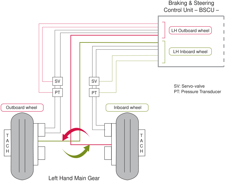
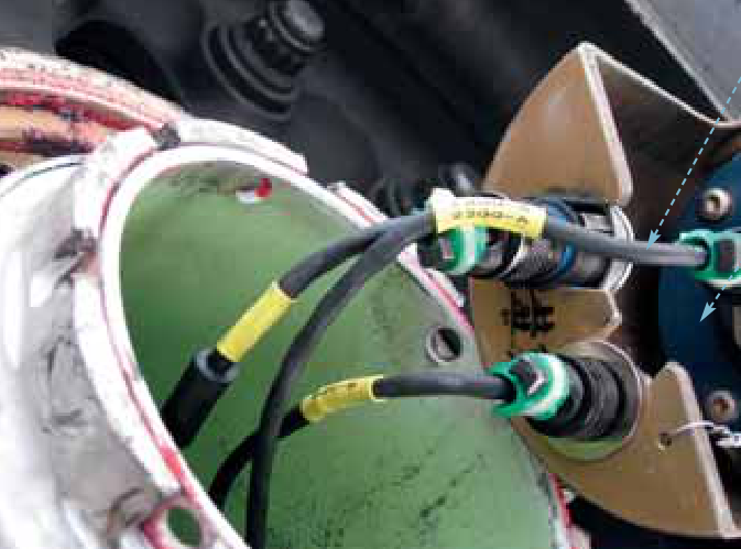
Figure 2 shows an actual cross connection on the right hand side main gear. The cable labelled 19GG-A/22GG-A connected to the tachometer (the blue cylindrical equipment
which can be partially seen on the right hand side of the picture), should in fact have been the cable 20GG-A/21GG-A.
Cross connected cable
Tachometer
Figure 2: Picture of tachometer cross connections
- Even if only two cases have been reported to Airbus, it is worth mentioning the other type of cross connections experienced so far.
It involves the connections to the servo-valves, as shown on figure 3.
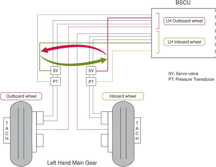
The lower number of cases that have been reported can be explained by the fact that the flanges supporting the servo-valve cables have different lengths. This type of cross connections are thus more difficult to realize.
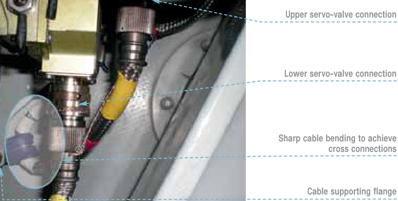
It shows that the flange supporting the cable to the lower servo-valve allows an easy connection only on the lower servo-valve.
In this case, the flange forced the cable wrongly connected to the upper servo-valve to make an excessively sharp bend.
Figure 4 shows an example of servo-valve cross connections.
3 Existing measures on the Single Aisle aircraft family
Section titled “3 Existing measures on the Single Aisle aircraft family”The Braking & Steering Control Unit – BSCU – (3GG), the servo-valves (15 GG, 16 GG, 17GG, 18GG) and the tachometers (19GG, 20GG, 21GG, 22GG) are the key components of the braking system. They must be properly connected to ensure efficient braking.
The BSCU compares each wheel speed to a computed reference speed and releases associated brake pressure if need be.
In case of cross connections , the braking performance will not be impacted as long as the anti-skid function is not activated. If the anti-skid function is activated , the BSCU will release the brake pressure on the opposite wheel, while maintaining the brake pressure on the already skidding wheel. The braking performance will then be significantly affected.
Note: Use of differential braking to correct the yaw tendency might be useless in this case, as the anti-skid system still provides braking orders to the wrong wheel.
In the majority of the reported cases, cross connections were evidenced further to tyres abnormal wear (flat spots) or bursts, and did not lead to serious incidents. However in a few cases these cross connections led to runway excursions.
This is why it is important to keep in mind existing measures.
The Aircraft Maintenance Manual – AMM – task 32-42-00-720-002 is specifically designed to detect cross connections.
AMM indicates in a specific note that: “You must do this test if there is a risk of wiring cross connections between two tachometers (replacement of the MLG or of the electrical harness of the MLG)”.
Should there be cross connections and an antiskid function activation during the landing roll, the crew will perceive two things:
-
A yawing tendency, and
-
An unusually small deceleration.
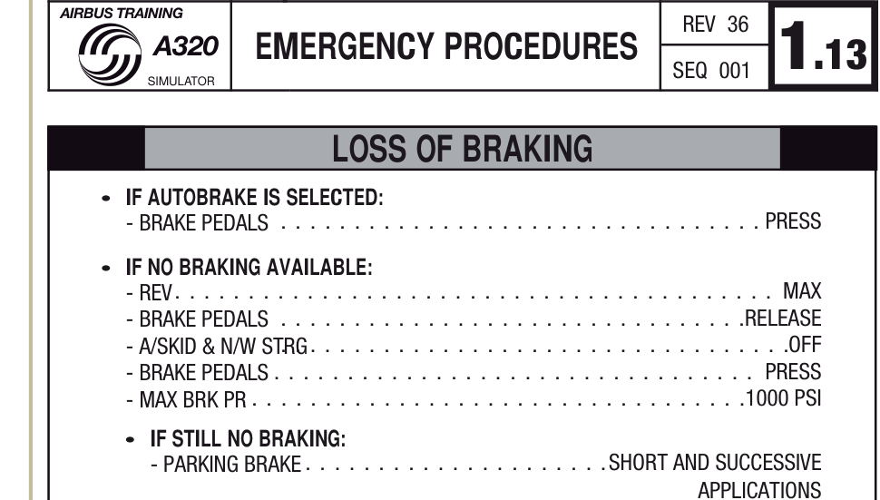
While controlling the lateral trajectory, if the aircraft’s deceleration rate is perceived as significantly below expectation, the crew must apply the Loss of Braking “memory item” procedure shown on figure 5.
It is worth mentioning that in these circumstances, it might be appropriate for the flight crew to maintain full reverse thrust below the SOP minimum recommended speed for full reverse use. The Standard Operating Procedure for Landing will be updated accordingly at the next general revision to indicate that, in case of emergency, maximum reverse thrust might be used until a complete stop.
The procedure calls for the anti-skid function to be turned OFF, thereby eliminating the major consequence of the cross connections.
4 Maintenance documentation improvements
Section titled “4 Maintenance documentation improvements”Recently, the AMM task 32-42-00-720-002 has been amended to include the monitoring of the brake’s wear pin and brake unit deflection, in addition to the previous monitoring of the brake’s piston movements, as additional means to determine proper brake operation.
6 Conclusion
Section titled “6 Conclusion”Crossed cables in the braking system have, in the past, caused incidents. It is therefore important to comply strictly with the published maintenance procedure.
Pilots facing a situation where the airplane yaws to one side and the aircraft’s deceleration rate is perceived as significantly below normal, may suspect brake cross connections. They should apply the Loss of Braking “memory item”, which calls for the anti-skid function to be turned OFF.
This task is now also required further to the installation of servo-valves.
REFERENCE
Section titled “REFERENCE”5 Future improvements
Section titled “5 Future improvements”Operator Information Telex (OIT) ref 999.0133/07/LB Rev 01 issued on the 30[th] of April 2008, reminds the operators to strictly adhere to the AMM task 32-42-00-720-002 “Functional Test of Tachometers” whenever it needs to be applied.
-
The Trouble Shooting Manual (TSM) will be enhanced to include an entry point in case of tyre flat spot(s), to look for possible cross connections
-
On the Single Aisle (SA) family, cable colour coding is currently under review to avoid crossing cables.
Note: All SA family changes
-
introduced (addition of warnings in AMM, monitoring of the brake’s wear pin and brake unit deflection to determine brake operation)
-
planned (TSM entry in case of tyre flat spots)
• or under review (cable colour coding) are being considered as well on the other families of Airbus aircraft fitted with boogie gears. On these types of landing gear, the consequences of cross connections are reduced compared to the diabolo versions.
来源: Airbus Safety First 网址: https://safetyfirst.airbus.com/braking-system-cross-connections/ 发布日期: 2009-02-14 期刊期号: 2009-02 类别: 档案 PDF: 原始 PDF
作者:Thierry THOREAU 飞行安全总监
本文将介绍:
- 两类已报告的交叉连接及其后果
多年来,刹车系统交叉连接已引发多起事故。空客机队中最严重的一起案例中,飞机在刹车系统交叉连接后从延伸跑道中心线约150英尺处停下。随即启动紧急撤离,所有人员安全脱险,未造成重伤。飞机受到了一定程度的损坏。
-
现有的预防措施
-
缓解这些问题的操作程序
-
以及已实施或计划实施的改进措施
对这些可能的维护错误加深认识将有助于避免或减轻后续事件。
-
2 单通道系列飞机报告的事件类型
-
已报告数起主起落架(MLG)转速表交叉连接的案例。这些交叉连接发生在机轮轴层面,如图1所示。
图2展示了右侧主起落架上的实际交叉连接。标有19GG-A/22GG-A的电缆连接到转速表(可在图片右侧部分看到蓝色圆柱形设备),但实际应该连接的是20GG-A/21GG-A电缆。
交叉连接的电缆
转速表
图2:转速表交叉连接实物图
- 尽管只向空客报告了两起此类事件,但另一种类型的交叉连接也值得关注。
该类型涉及伺服阀的连接,如图3所示。
报告案例数量较少的原因在于,支撑伺服阀电缆的凸缘具有不同长度,因此此类交叉连接更难实现。
图中显示,连接至下伺服阀的凸缘仅能方便地连接下伺服阀。
在错误连接的情况下,上伺服阀的电缆被迫形成过大弯角。
图4展示了伺服阀交叉连接的一个实例。
3 单通道系列飞机现有措施
Section titled “3 单通道系列飞机现有措施”刹车与转向控制组件(BSCU)(3GG)、伺服阀(15GG、16GG、17GG、18GG)和转速表(19GG、20GG、21GG、22GG)是刹车系统的关键部件。它们必须正确连接以确保有效的刹车性能。
BSCU 将每个机轮速度与计算得出的参考速度进行比较,必要时释放相应的刹车压力。
若发生交叉连接,只要防滑功能未启动,刹车性能将不受影响。若防滑功能启动,BSCU 将在已打滑的机轮上保持刹车压力,同时释放对侧机轮的刹车压力。此时刹车性能将受到显著影响。
注意:在这种情况下,使用差动刹车修正偏航趋势可能无效,因为防滑系统仍在向错误的机轮发出刹车指令。
在大多数报告的案例中,交叉连接是通过轮胎异常磨损(平点)或爆胎发现的,并未导致严重事故。然而在少数案例中,这些交叉连接导致了跑道偏出。
正因如此,牢记现有措施至关重要。
《飞机维护手册》(AMM)任务 32-42-00-720-002 专门用于检测交叉连接。
AMM 在专门说明中指出:“若存在两个转速表之间线路交叉连接的风险(更换主起落架或主起落架电气线束时),则必须执行此测试。”
若发生交叉连接且在着陆滑跑期间防滑功能启动,机组会察觉两件事:
-
偏航趋势,以及
-
异常的减速过小。
在控制侧向轨迹时,若飞机减速率明显低于预期,机组必须执行图5所示的“刹车失效”记忆项目程序。
值得指出的是,在这种情况下,飞行机组可在标准操作程序(SOP)推荐的最低全反推使用速度以下保持全反推。着陆标准操作程序将在下次全面修订时相应更新,明确在紧急情况下可使用最大反推直至完全停止。
该程序要求关闭防滑功能,从而消除交叉连接的主要后果。
4 维护文件改进
Section titled “4 维护文件改进”最近,AMM 任务 32-42-00-720-002 已修订,在原有监测刹车活塞运动的基础上,增加了对刹车磨损销和刹车组件偏转的监测,作为判断刹车正常工作的附加手段。
刹车系统中的交叉电缆过去曾导致事故。因此,严格遵守已发布的维护程序非常重要。
飞行员遇到飞机偏航至一侧且飞机减速率明显低于正常值的情况时,可怀疑存在刹车交叉连接。他们应执行”失去刹车”的”记忆项目”,该程序要求关闭防滞功能。
由于伺服阀的安装,此任务现在也被列为必做项目。
5 未来改进
Section titled “5 未来改进”运营者信息通告(OIT)编号 999.0133/07/LB Rev 01,发布于 2008 年 4 月 30[日],提醒运营者在需要执行 AMM 任务 32-42-00-720-002”转速表功能测试”时,必须严格遵守。
-
《故障排除手册》(TSM)将增加一个入口点,以便在出现轮胎扁平区域时,排查可能的交叉连接
-
在单通道(SA)系列上,电缆颜色编码目前正在审查中,以避免电缆交叉。
注:所有 SA 系列变更
-
已实施(AMM 中增加警告、监测刹车磨损销和刹车组件偏转以判断刹车工作状态)
-
已计划(轮胎扁平区域时的 TSM 入口)
-
或正在审查中(电缆颜色编码)
均正在考虑应用于其他装有双轮式起落架的空客机型。在此类型起落架上,交叉连接的后果与 diabolo 版本相比较轻。