Lining Up with the Correct Glide Slope
Source: Airbus Safety First URL: https://safetyfirst.airbus.com/lining-up-with-the-correct-glide-slope/ Published: 2021-12-09 Category: Flight Ops, approach, G/S, glideslope, ILS, landing PDF: Original PDF

The Instrument Landing System (ILS) is accurate and reliable, but the ILS antenna design today causes secondary glide slopes to appear above the primary glide slope. Flight crews must be aware of this phenomenon to prevent unwanted aircraft behavior during an ILS glide slope capture.
This article explains the phenomenon of secondary glide slopes and their effect on aircraft systems. It provides and that show how crews can guidance examples flight prevent capturing a secondary glide slope. It also describes the on Airbus aircraft that limit the effect of an protections unintended secondary glide slope capture on the aircraft trajectory.
This article is also available on safetyfirst.airbus.com and on the Safety first app for iOS and Android devices.
Capturing a secondary glide slope can lead to unexpected aircraft behavior. It is important for flight crew to be aware of the phenomenon and to know how to prevent secondary glide slope capture. Some typical scenarios, based on real cases, with their associated effects on the aircraft trajectory and their prevention means are described below.
CASE 1: EXCESSIVE PITCH DOWN DURING ILS GLIDE SLOPE INTERCEPTION FROM ABOVE
Section titled “CASE 1: EXCESSIVE PITCH DOWN DURING ILS GLIDE SLOPE INTERCEPTION FROM ABOVE”The first case happens during an ILS glide slope interception from above. The aircraft descends in —OP DES- guidance mode (fig.1). The air traffic controller clears the flight crew for approach. ① The flight crew consequently presses the -APPR- pushbutton. ② The PFD indicates a glide slope below the aircraft, as expected by the flight crew. ③ A few seconds later, the —G/S*- mode engages and the autopilot orders a pitch down command toward the glide slope. The pitch down command continues until it reaches the 13° pitch down limit for autopilot disconnection ④. The flight crew must take over to recover the situation and perform a go-around.
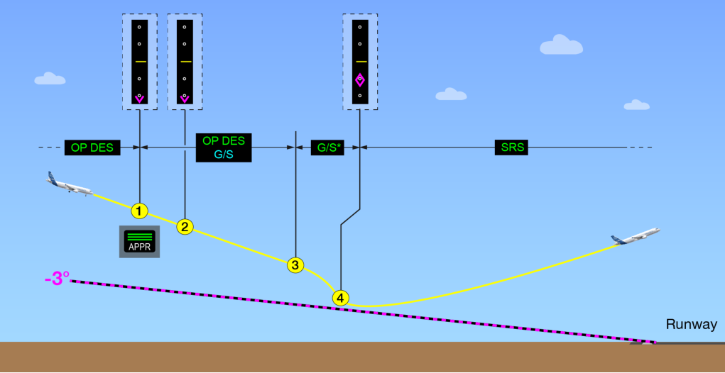
(fig.1) Event of excessive pitch down during ils glide slope interception from above
A secondary glide slope capture was the cause of this event
Section titled “A secondary glide slope capture was the cause of this event”Analysis of the data from the flight recorders enabled us to identify that this excessive pitch down order was caused by an initial capture of a secondary glide slope that caused undue early engagement of the —G/S*- guidance mode. Before explaining what happened, we need to know what the secondary glide slope phenomenon is.
ILS Secondary Glide Slope Phenomenon
Section titled “ILS Secondary Glide Slope Phenomenon”Secondary glide slopes are an inevitable characteristic due to the ILS antenna design. When an aircraft flies well above the main glide slope, the glide slope deviations displayed on the PFD will refer to the nearest glide slope, which may be a secondary glide slope instead of the primary one. This can lead both the flight crew and the autopilot to erroneously consider the secondary glide slope as the reference for the final descent.
There are several types of ILS glide slope antennas that use different technologies. They can be classified into two theoretical categories: “Inverted” glide slope and “repeated” glide slope. This considers the associated impact on the autopilot behavior and the indications observed by the flight crew.
ILS with “inverted” secondary glide slopes
Section titled “ILS with “inverted” secondary glide slopes”This category of glide slope antennas inverts the orientation of the glide slope at every other glide slope. For example, in the case of a -3° glide slope, secondary glide slopes exist at -9°, -15°, -21° and every other 6°, but the glide slopes at -9°, -21° and every other 12° are inverted. The PFD glide slope deviations are inverted for these glide slopes, i.e. the aircraft is seen above the glide slope when it is below and vice versa (fig.2).
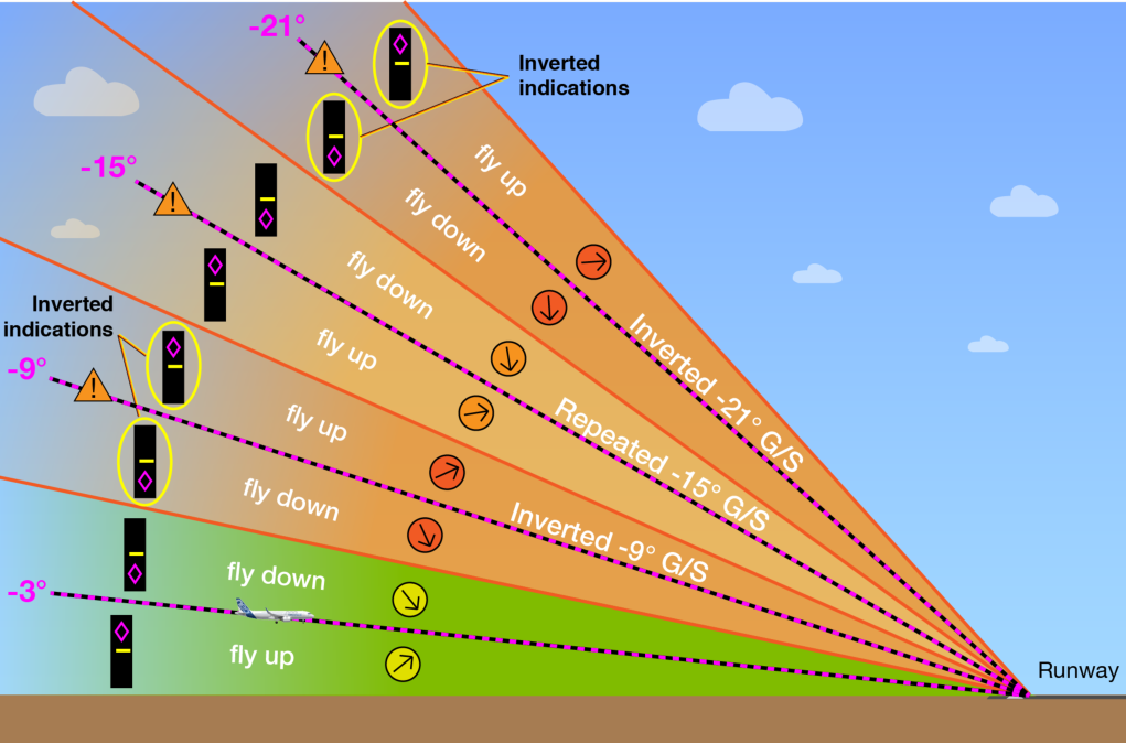
(fig.2) Theoretical representation of a main -3° ILS glide slope and its inverted secondary glide slopes (only the secondary glide slopes at -9°, -15°, and -21° are represented for clarity and the angles are represented at twice their actual size)
ILS with only “repeated” secondary glide slopes
Section titled “ILS with only “repeated” secondary glide slopes”This category of antennas has only repeated glide slopes above the main glide slope (fig.3). For example, in the case of a -3° glide slope, repeated secondary glide slopes exist at -9°, -15°, -21° and every other 6°.
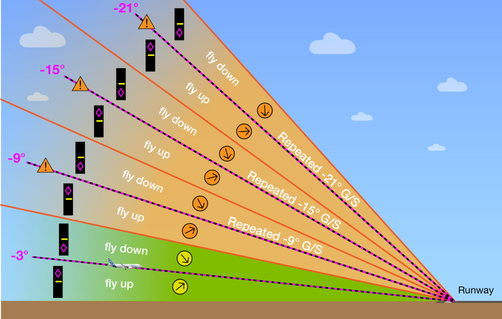
(fig.3) Theoretical representation of a main -3° ILS glide slope and its repeated secondary glide slopes (only the secondary glide slopes at -9°, -15°, and -21° are represented for clarity and the angles are represented at twice their actual size)
There is no way for flight crews to know which category of ILS antenna (either with “inverted” or “only repeated”) is used at their destination airport.
Note that no cases of unexpected behavior due to ILS with “only repeated” glide slopes were reported to Airbus, therefore the examples shown only describe scenarios of ILS with inverted glide slopes. Variable measured signal characteristics at the boundary between two glide slopes Test flights performed to analyze the secondary glide slope structures showed that the real characteristics of the glide slopes may differ from the above theory, in particular in the boundary region between two glide slopes (shown as amber lines in fig.2 and fig.3 ). Therefore, it is difficult to predict the behavior of the autopilot in these zones.
Possible inappropriate engagement of** —G/S*- **when crossing the boundary between two glide slopes
Section titled “Possible inappropriate engagement of** —G/S*- **when crossing the boundary between two glide slopes”When an aircraft crosses the boundary between two glide slopes (at approximately -6°, -12°, -18°, etc…), temporary deviation “jumps” and/or a false deviation value of zero can trigger inappropriate engagement of the —G/S*capture mode. This can happen when the approach guidance modes are armed, meaning that the -APPR (LAND for A300-600/A310) pushbutton was previously pressed. The physical characteristics of the glide slope or the speed and angle at which the aircraft crosses the boundary, will influence if engagement occurs. Note that this phenomenon is possible for both the “repeated” and “inverted” types of secondary glide slope. Therefore, it is difficult to anticipate the autopilot behavior when crossing the boundary between two glide slopes.
The ICAO envelope for glide slope signal quality
Section titled “The ICAO envelope for glide slope signal quality”ICAO guidelines provide recommendations for ensuring the quality of the ILS glide slope signal. Periodic checks on all ILS equipped runways ensure that the ILS signal quality is at the required level inside a defined envelope.
Capturing the ILS glide slope within this envelope ensures that the aircraft is within the area of influence for the primary glide slope. It also ensures that the ILS signal is of sufficient quality to ensure a normal ILS glide slope capture. The ICAO envelope (fig.4) is within:
-
10 NM from the runway threshold
-
+/-8 ° laterally from the runway centerline
-
0.3 x Θ up to 1.75 x Θ (Θ, being the nominal glide path angle).
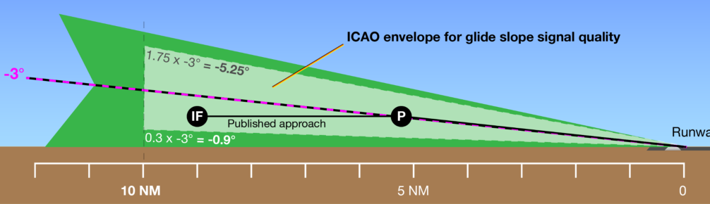
- (fig.4) Example of the ICAO envelope for an ILS with a -3° glide slope
Analysis of the excessive pitch down event
Section titled “Analysis of the excessive pitch down event”With the secondary glide slope theory in mind, we can review the scenario of the event to better understand what happened.
The aircraft is in —OP DES- (LVL/CH for A300-600/A310) mode (fig.5). ① The flight crew presses the -APPR- (LAND for A300-600/A310) pushbutton well above the -3° glide slope, within the -9° zone of influence. The aircraft is nearer to the -9° secondary glide slope but far enough from it so that the —G/S— mode is armed but not engaged. ② The inverted glide slope deviations mean the flight crew cannot detect that their aircraft is in the zone of influence of an inverted secondary glide slope. The glide slope indicated below the aircraft is as expected
by the flight crew. ③ When the aircraft crosses the -6° boundary between the -3° and -9° glide slopes, a temporary false deviation value of zero received by the MMR triggers the undue engagement of the —G/S*- mode. Therefore, the autopilot orders a pitch down command toward the -3° glide slope. As the aircraft is flying high above the -3°, there is sufficient time for the pitch to reach the 13° pitch down limit for autopilot disconnection ④. In manual flight, the flight crew must take over to recover the situation and perform a go-around.
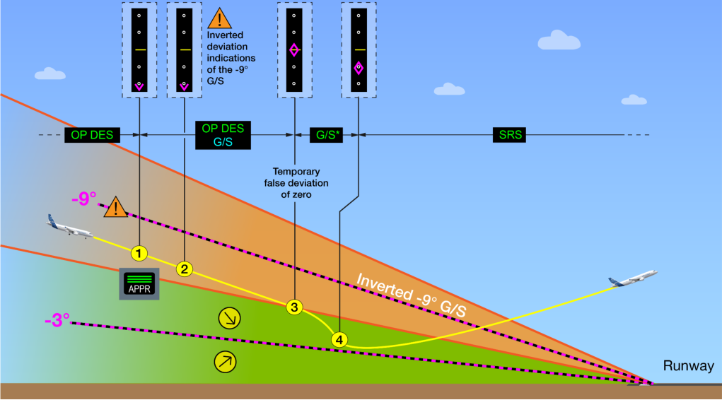
- (fig.5) Excessive pitch down due to undue G/S* activation during ILS glide slope interception from above
Prevention: Quick check of the aircraft position before pressing the APPR pushbutton when intercepting a glide slope from above
Section titled “Prevention: Quick check of the aircraft position before pressing the APPR pushbutton when intercepting a glide slope from above”When intercepting the glide slope from above, the flight crew should ensure that the aircraft is below the upper boundary of the main glide slope before they press the -APPR- (LAND for A300-600/A310) pushbutton. This boundary is located at approximately twice the value of the primary glide slope angle (approximately -6° in our example). This ensures that the capture will be done on the correct glide slope. As a rule of thumb, a quick altitude vs. distance check can be done to ensure that the aircraft is below the upper boundary of the main glide slope. The aircraft altitude above airport elevation (in ft) should be less than 6 times the distance to runway (in NM) multiplied by 100 (fig.6) :
h(ft AAL) < 6 x d (NM) x 100
Section titled “h(ft AAL) < 6 x d (NM) x 100”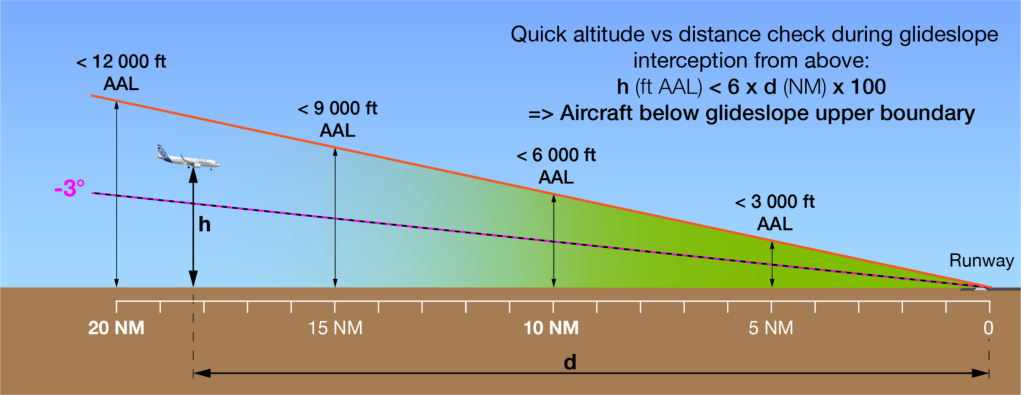
(fig.6) For ILS glide slope interception from above, a quick altitude vs. distance check ensures that the aircraft is below the upper boundary of the primary glide slope before pressing the APPR (LAND for A300-600/A310) pushbutton
Check of the glide slope in standard glide slope interception (from below)
Section titled “Check of the glide slope in standard glide slope interception (from below)”Similarly to the above quick check, the flight crew can estimate if they are intercepting the correct glide slope during a standard glide slope interception from below using the formula: h(ft AAL) = 3 x d (NM) x 100
FCOM procedure: guidance mode for glide interception from above
Section titled “FCOM procedure: guidance mode for glide interception from above”In the described event and in the next one, the flight crew uses the -OP DESguidance mode to intercept the glide slope from above. This is not recommended in the FCOM. As per the FCOM “Glide interception from above” procedure and the FCTM, after the aircraft is established on the localizer, the flight crew should press the APPR pushbutton, set the FCU altitude above the aircraft altitude, and then select the -V/S- mode to intercept the glide slope.
CASE 2: EXCESSIVE PITCH UP DURING ILS GLIDE SLOPE INTERCEPTION FROM ABOVE
Section titled “CASE 2: EXCESSIVE PITCH UP DURING ILS GLIDE SLOPE INTERCEPTION FROM ABOVE”In this second case, an aircraft also intercepts the glide slope from above (fig.7). ① The flight crew presses the APPR (LAND for A300-600/A310) pushbutton but does not set the FCU altitude target above the aircraft altitude, because it is usually requested by the SOP for an ILS approach. The aircraft converges toward the -3° glide slope, but reaches the target altitude before the —G/S*- can engage. ② The aircraft levels off and starts to diverge from the -3° glide slope and to converge with the -9° secondary glide slope. ③ When crossing the -6° boundary between the -3° and -9° glide slopes, the MMR receives a temporary false deviation value of zero, but it is not sufficient to engage the —G/S*- mode. ④ The -9° glide slope is inverted, and as a result, the glide slope deviation indications show the glide slope below the aircraft. ⑤ When the aircraft crosses the -9° secondary glide slope, the —G/S*- guidance mode engages. The autopilot then commands a pitch up when the aircraft crosses the -9° glide slope, due to its inversion. In this case, the flight crew has no choice but to perform a go-around ⑥.
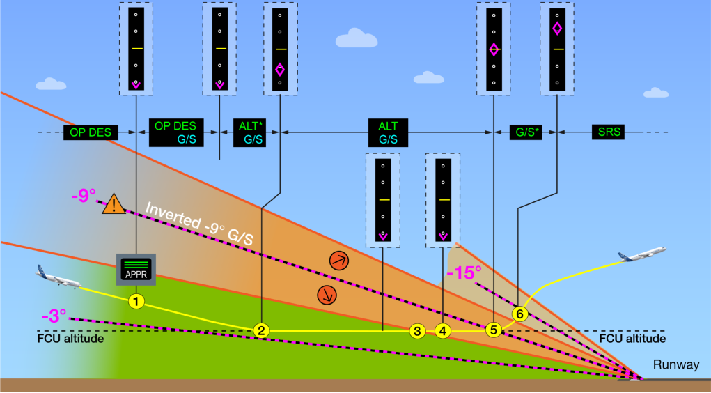
(fig.7) Excessive pitch up command due to inverted secondary glide slope capture
Prevention: Correct FCU altitude setting during glide interception from above
Section titled “Prevention: Correct FCU altitude setting during glide interception from above”The “glide interception from above” FCOM procedure requests the flight crew to select the FCU altitude above aircraft altitude. This should be done after the flight crew presses the -APPR- (LAND for A300-600/A310) pushbutton to prevent unwanted _ALT*- engagement and possible level-off that can lead to the capture of a secondary glide slope as shown in this example. This important step of the procedure can prevent such an occurrence.
CASE 3: UNEXPECTED PITCH UP DURING A DISCONTINUED APPROACH
Section titled “CASE 3: UNEXPECTED PITCH UP DURING A DISCONTINUED APPROACH”① The flight crew needs to interrupt their glide slope interception from above at the request of ATC, due to unavailability of the runway (fig.8). ② The flight crew presses the -VS/FPA- knob-selector to level off but does not press the -APPRpushbutton to disarm the —G/S— guidance mode, which is usually expected during a discontinued approach. The aircraft levels off as expected. This now follows the the same scenario as described in case 2: ③ When the aircraft crosses the -6° boundary between the -3° and -9° glide slope, the duration of the temporary false deviation value of zero is short enough not to engage the —G/Smode. ④ When the aircraft crosses the -9° glide slope, the —G/S- mode engages and commands a pitch up due to the inversion of the secondary glide slope. ⑤ The flight crew must take over and perform a go-around.
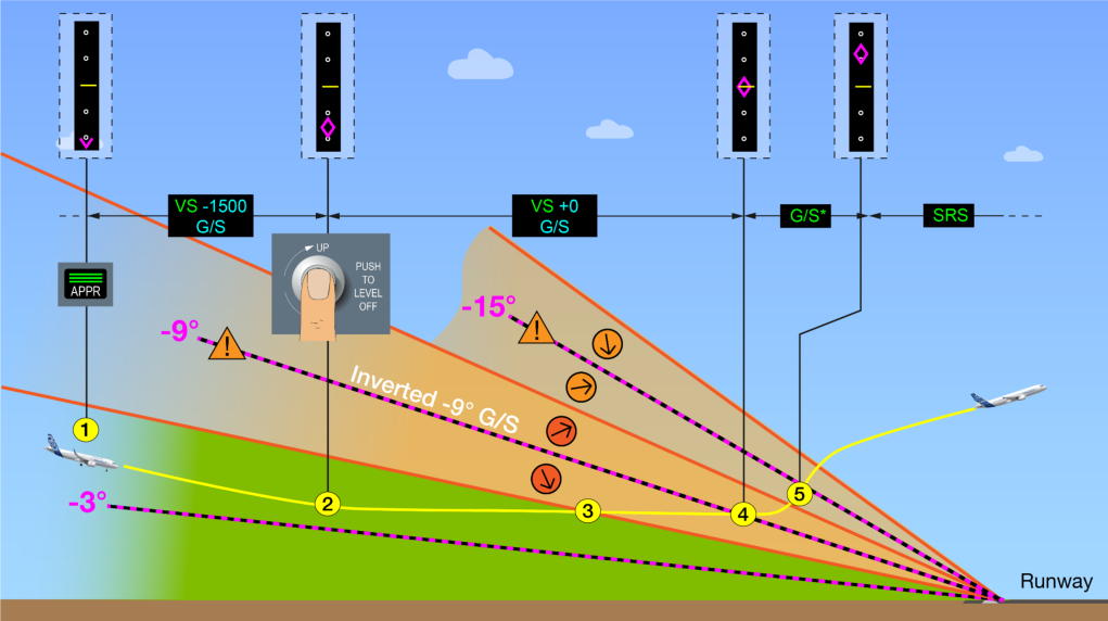
- (fig.8) Unexpected pitch up during a discontinued approach
Prevention: Disarming of the approach guidance mode during discontinued approach procedure
Section titled “Prevention: Disarming of the approach guidance mode during discontinued approach procedure”After the flight crew announces “CANCEL APPROACH”, they must remember to press the -APPR- pushbutton to disarm the —G/S— guidance mode as per the “discontinued approach” SOP. This will prevent engagement of the _G/S*- and —G/S— modes on a secondary ILS glide slope.
AVAILABLE PROTECTIONS
Section titled “AVAILABLE PROTECTIONS”Airbus developed some protections to limit the Flight Path Angle (FPA) in the case of a secondary glide slope capture by doing some modification on the autopilot flight guidance laws. These are available on A330, A340, A350, and A380 aircraft and limit the maximum Flight Path Angle (FPA) between 0° and -6° in _G/S*- mode. A320neo family aircraft have FPA protection in both _G/S*- and —G/S— modes.
The protections referred to above are not available on A220, A300, A310, and A320ceo aircraft at the time of publishing. The same protections will be introduced on A320ceo, and the protections that are already available on A330, A350, and A380 aircraft will be updated with the next Flight Guidance computer standard update to make these protections available in both _G/S*- and —G/S-modes. A similar protection will be added in the -GS- guidance mode of A220 aircraft at the opportunity of a future avionics build.
| Aircraft | Current Design | Current Design | Future Design | Future Design | Future Design |
|---|---|---|---|---|---|
| A320neo | —G/S*- and —G/S— | —G/S*- and —G/S— | Basic | Available | |
| Basic | |||||
| HJ1 or G1 | |||||
| A340 | —G/S*- | F3 | None | Not applicable | Not applicable |
| A350 | —G/S*- | —G/S*- and —G/S— | PRIM P13 | Q4 2021 | |
| Basic | |||||
| A380 | —G/S*- | —G/S*- and —G/S— | PRIM P13.5 | Q2 2022 | |
| P8 | |||||
Table 1: Availability of protections in —G/S*- and —G/S— guidance modes to prevent excessive pitch if a capture of a secondary glide slope occurs. Note: Data correct at time of publication in December 2021.
Contributors:
Section titled “Contributors:”Hélène CARROLS Accident/Incident Investigator Product Safety
Cedric DESCHEEMAEKER Product Safety Enhancement Manager Product Safety
Xavier DUREPAIRE Training & Flight Operations Expert Pilot Customer Support
Nicolas MARCONNET
Section titled “Nicolas MARCONNET”Avionics System Engineer Design Office
Secondary glide slopes are inevitable characteristics of ILS approaches. Flight crews must be aware of secondary glide slopes and their possible effect on the display of the glide slope deviations and on the aircraft trajectory. This will ensure that they react correctly in the case of a secondary glide slope capture. Flight crews can prevent a secondary glide slope capture by following the applicable FCOM SOP.
To intercept an ILS glide slope from above , the aircraft should be below the boundary between the primary glide slope and the first secondary glide slope (6° for a 3° glide slope). The flight crew should then press the -APPR- (LAND for A300-600/A310) pushbutton and ensure that the FCU altitude is set above the aircraft altitude.
In the case of a discontinued approach , after the “CANCEL APPROACH” callout, the flight crew should press the -APPR- (ALT. HLD for A300-600/A310) pushbutton to disarm the —G/S— guidance mode as per the SOP.
Lilian RONCERAY
Section titled “Lilian RONCERAY”Aircraft Control System Engineer Design Office
Airbus developed protections for the _G/S*- and —G/S— guidance modes to limit the flight path angle of the aircraft between 0° and -6°. This will prevent an excessive pitch command if an unwanted capture of a secondary glide slope occurs. These protections are available on many Airbus aircraft in _G/S*- guidance modes and will be made available for most of the Airbus fly-by-wire aircraft in both _G/S*- and —G/S— guidance modes on future flight guidance computer standards.
Safety first , 2021. Safety first is published by Airbus S.A.S. 1, rond point Maurice Bellonte - 31707 Blagnac Cedex/France.
Editor: Yannick Malinge, Chief Product Safety Officer.
Editorial team: Guillaume Estragnat, Vanessa Sadi, Gwyneth Duggan, Tim Roach.
- Reference: X00D16031905.
Photos by Airbus.
© Airbus S.A.S. 2021 – All rights reserved. Proprietary documents.
Section titled “© Airbus S.A.S. 2021 – All rights reserved. Proprietary documents.”来源: Airbus Safety First 网址: https://safetyfirst.airbus.com/lining-up-with-the-correct-glide-slope/ 发布日期: 2021-12-09 类别: 飞行运行, 进近, G/S, 下滑道, ILS, 着陆 PDF: 原始 PDF
仪表着陆系统(ILS)精确可靠,但当前的 ILS 天线设计会导致辅助下滑道出现在主下滑道上方。飞行机组必须了解这一现象,以防止在 ILS 下滑道截获过程中出现不希望的飞机行为。
本文解释了辅助下滑道现象及其对飞机系统的影响,并提供了相关指导示例,展示飞行机组如何防止截获辅助下滑道。此外还描述了空客飞机上限制意外截获辅助下滑道对飞机轨迹影响的保护措施。
本文也可在 safetyfirst.airbus.com 网站以及 iOS 和 Android 设备的 Safety First 应用中获取。
截获辅助下滑道可能导致意外的飞机行为。飞行机组了解这一现象并知道如何防止截获辅助下滑道非常重要。以下描述了一些基于真实案例的典型场景,以及它们对飞机轨迹的影响和预防措施。
案例 1:从上方截获 ILS 下滑道时出现过度俯仰向下
Section titled “案例 1:从上方截获 ILS 下滑道时出现过度俯仰向下”第一种情况发生在从上方截获 ILS 下滑道时。飞机以—OP DES-引导模式下降**(图 1)**。空管员同意飞机进近。① 飞行机组随即按下-APPR-按钮。② PFD 显示下滑道在飞机下方,符合飞行机组的预期。③ 几秒钟后,—G/S*-模式接通,自动驾驶发出朝向下滑道的俯仰向下指令。俯仰向下指令持续直到达到自动驾驶脱开的 13°俯仰限制④。飞行机组必须接管以恢复正常并执行复飞。
(图 1) 从上方截获 ILS 下滑道时出现过度俯仰向下的事件
辅助下滑道截获是此次事件的原因
Section titled “辅助下滑道截获是此次事件的原因”对飞行记录器数据的分析使我们能够确定,这一过度俯仰向下指令是由最初截获辅助下滑道导致 —G/S*-引导模式过早接通而引起的。在解释所发生的情况之前,我们需要了解辅助下滑道现象。
ILS 辅助下滑道现象
Section titled “ILS 辅助下滑道现象”辅助下滑道是 ILS 天线设计的固有特性。当飞机飞行高度远高于主下滑道时,PFD 上显示的下滑道偏差将参照最近的下滑道,这可能是辅助下滑道而非主下滑道。这可能导致飞行机组和自动驾驶都错误地将辅助下滑道作为最后下降的参考。
ILS 下滑道天线有多种类型,采用不同的技术。它们可分为两大理论类别:“反转”下滑道和“重复”下滑道。这涉及对自动驾驶行为和飞行机组观察到的指示的相应影响。
带有“反转”辅助下滑道的 ILS
Section titled “带有“反转”辅助下滑道的 ILS”此类下滑道天线每隔一个下滑道就会反转其方向。例如,对于 -3° 的下滑道,辅助下滑道存在于 -9°、-15°、-21° 及每隔 6° 的位置,但 -9°、-21° 及每隔 12° 的下滑道是反转的。PFD 上的下滑道偏差在这些下滑道处是反转的,即当飞机在下滑道下方时显示为在上方,反之亦然**(图 2)**。
(图 2) 主 -3° ILS 下滑道及其反转辅助下滑道的理论表示(仅为清晰起见展示了 -9°、-15° 和 -21° 处的辅助下滑道,且角度以实际大小两倍表示)
仅带有“重复”辅助下滑道的 ILS
Section titled “仅带有“重复”辅助下滑道的 ILS”此类天线在主下滑道上方只有重复的下滑道**(图 3)**。例如,对于 -3° 的下滑道,重复的辅助下滑道存在于 -9°、-15°、-21° 及每隔 6° 的位置。
(图 3) 主 -3° ILS 下滑道及其重复辅助下滑道的理论表示(仅为清晰起见展示了 -9°、-15° 和 -21° 处的辅助下滑道,且角度以实际大小两倍表示)
飞行机组无法知道目的地机场使用的是哪一类 ILS 天线(“反转”或“仅重复”)。
请注意,没有接到过关于仅带“重复”下滑道的 ILS 意外行为的报告,因此以下示例仅描述带有反转下滑道的 ILS 场景。两个下滑道边界处的测量信号特性变化 为分析辅助下滑道结构而进行的试飞表明,实际下滑道特性可能与上述理论不同,特别是在两个下滑道之间的边界区域(如图 2 和图 3 中的琥珀色线条所示)。因此,难以预测自动驾驶在这些区域的行为。
穿越两个下滑道边界时可能导致 *—G/S— 不恰当衔接
Section titled “穿越两个下滑道边界时可能导致 *—G/S— 不恰当衔接”当飞机穿越两个下滑道之间的边界(约 -6°、-12°、-18° 等)时,暂时的偏差”跳变”和/或虚假零偏差值可能触发 —G/S*— 捕获模式的不恰当衔接。此情况可能发生在进近引导方式已预位的情况下,即之前已按下 APPR(A300-600/A310 为 LAND)按钮。下滑道的物理特性或飞机穿越边界的速度和角度,将影响是否发生衔接现象。需注意,此现象在”重复型”和”倒置型”二次下滑道中均可能发生。因此,很难预知飞机穿越两个下滑道边界时自动驾驶的行为。
ICAO 下滑道信号质量包线
Section titled “ICAO 下滑道信号质量包线”ICAO 指南为确保 ILS 下滑道信号质量提供了建议。对所有配备 ILS 的跑道进行定期检查,确保 ILS 信号质量在规定包线内达到要求等级。
在此包线内捕获 ILS 下滑道可确保飞机处于主下滑道的影响范围内,同时确保 ILS 信号质量足以实现正常的 ILS 下滑道捕获。ICAO 包线**(图 4)**的范围为:
-
距跑道入口 10 NM 以内
-
距跑道中线 侧向 +/-8° 以内
-
0.3 × Θ 至 1.75 × Θ(Θ 为名义下滑道角度)。
- (图 4) -3° 下滑道的 ILS 的 ICAO 包线示例
过度低头事件分析
Section titled “过度低头事件分析”基于二次下滑道理论,我们可以回顾该事件场景以更好地理解所发生的情况。
飞机处于 —OP DES—(A300-600/A310 为 LVL/CH)模式**(图 5)**。① 机组在远高于 -3° 下滑道的位置(在 -9° 影响范围内)按压 APPR(A300-600/A310 为 LAND)按钮。飞机更接近 -9° 二次下滑道,但距其足够远,因此 —G/S— 方式已预位但尚未衔接。② 倒置下滑道偏差意味着机组无法检测到飞机处于倒置二次下滑道的影响范围内。飞机下方的下滑道指示与机组预期一致。③ 当飞机穿越 -3° 和 -9° 下滑道之间的 -6° 边界时,MMR 收到的暂时虚假零偏差值触发了 —G/S*— 方式的不当衔接。因此,自动驾驶发出朝向 -3° 下滑道的低头指令。由于飞机当时在 -3° 上方足够高的高度,有足够时间使俯仰达到自动驾驶脱开的 13° 低头限制。④ 在人工飞行时,机组必须接手恢复状况并执行复飞。
- (图 5) 从上方截获 ILS 下滑道时因不当 G/S* 激活导致的过度低头
预防:从上方截获下滑道时按压 APPR 按钮前的快速位置检查
Section titled “预防:从上方截获下滑道时按压 APPR 按钮前的快速位置检查”从上方截获下滑道时,机组应确保飞机在按压 APPR(A300-600/A310 为 LAND)按钮前已低于主下滑道的上限边界。该边界位于主下滑道角度值的大约两倍处(在本例中约为 -6°)。这可确保在正确的下滑道上进行捕获。作为经验法则,可进行快速高度与距离检查以确保飞机低于主下滑道的上限边界。飞机高于机场标高的高度(英尺)应小于至跑道距离(海里)的 6 倍乘以 100 (图 6):
h(ft AAL)< 6 × d(NM)× 100
Section titled “h(ft AAL)< 6 × d(NM)× 100”
(图 6) 从上方截获 ILS 下滑道时,快速高度与距离检查可确保在按压 APPR(A300-600/A310 为 LAND)按钮前飞机低于主下滑道的上限边界
标准下滑道截获(从下方)的下滑道检查
Section titled “标准下滑道截获(从下方)的下滑道检查”与上述快速检查类似,机组可使用公式估算在从下方进行标准下滑道截获时是否正在截获正确的下滑道:h(ft AAL)= 3 × d(NM)× 100
FCOM 程序:从上方截获下滑道的引导模式
Section titled “FCOM 程序:从上方截获下滑道的引导模式”在所描述的事件和接下来的事件中,机组使用 -OP DES 引导模式从上方截获下滑道。FCOM 中不推荐这样做。根据 FCOM “从上方截获下滑道”程序和 FCTM,在飞机建立航向道后,机组应按下 APPR 按钮,将 FCU 高度设置为高于飞机高度,然后选择 V/S 模式来截获下滑道。
案例 2:从上方截获 ILS 下滑道时过度抬头
Section titled “案例 2:从上方截获 ILS 下滑道时过度抬头”在第二个案例中,飞机同样从上方截获下滑道 (图7)。① 机组按下 APPR(A300-600/A310 为 LAND)按钮,但未将 FCU 目标高度设置为高于飞机高度,因为这通常是 ILS 进近 SOP 的要求。飞机向 -3° 下滑道收敛,但在 —G/S*- 模式可以接通之前就已到达目标高度。② 飞机平飞并开始偏离 -3° 下滑道,向 -9° 副下滑道收敛。③ 当穿越 -3° 和 -9° 下滑道之间的 -6° 边界时,MMR 接收到一个临时的零偏差假值,但这不足以接通 —G/S*- 模式。④ -9° 下滑道是反转的,因此下滑道偏差指示显示下滑道在飞机下方。⑤ 当飞机穿越 -9° 副下滑道时,—G/S*- 引导模式接通。由于副下滑道的反转,自动驾驶在飞机穿越 -9° 下滑道时指令一个抬头动作。在这种情况下,机组别无选择,只能执行复飞 ⑥。
(图7) 由于截获反转的副下滑道导致的过度抬头指令
预防:从上方截获下滑道时正确设置 FCU 高度
Section titled “预防:从上方截获下滑道时正确设置 FCU 高度”“从上方截获下滑道”的 FCOM 程序要求机组将 FCU 高度设置为高于飞机高度。这应在机组按下 APPR(A300-600/A310 为 LAND)按钮之后进行,以防止不希望的 ALT* 接通和可能的平飞,而平飞可能导致截获副下滑道,如本例所示。程序中的这一重要步骤可以防止此类事件的发生。
案例 3:中断进近期间意外的抬头
Section titled “案例 3:中断进近期间意外的抬头”① 由于跑道不可用,机组需要在 ATC 的要求下中断从上方截获下滑道 (图8)。② 机组按下 VS/FPA 旋钮选择器以平飞,但未按下 APPR 按钮来断开 —G/S— 引导模式,这在中断进近时通常是预期的。飞机按预期平飞。这现在遵循案例 2 中描述的相同场景:③ 当飞机穿越 -3° 和 -9° 下滑道之间的 -6° 边界时,临时零偏差假值的持续时间短到不足以接通 —G/S* 模式。④ 当飞机穿越 -9° 下滑道时,—G/S*- 模式接通并由于副下滑道的反转而指令抬头。⑤ 机组必须接管并执行复飞。
- (图8) 中断进近期间意外的抬头
预防:中断进近程序期间断开进近引导模式
Section titled “预防:中断进近程序期间断开进近引导模式”机组宣布 “CANCEL APPROACH” 后,必须记住按下 APPR 按钮以断开 —G/S— 引导模式,如同 “中断进近” SOP 中所要求的。这将防止在副 ILS 下滑道上接通 G/S* 和 —G/S— 模式。
现有的保护措施
Section titled “现有的保护措施”空客通过修改自动驾驶飞行引导律开发了一些保护措施,以限制在截获副下滑道情况下的飞行轨迹角(FPA)。这些保护措施适用于 A330、A340、A350 和 A380 飞机,并在 G/S* 模式下将最大飞行轨迹角(FPA)限制在 0° 至 -6° 之间。A320neo 系列飞机在 G/S* 和 —G/S— 模式下都具有 FPA 保护。
上述保护措施在出版时尚不适用于 A220、A300、A310 和 A320ceo 飞机。相同的保护措施将引入 A320ceo,而 A330、A350 和 A380 飞机上已有的保护措施将在下一次飞行引导计算机标准更新中进行更新,以使这些保护措施在 G/S* 和 —G/S— 模式下均可用。类似的保护措施将在未来航电系统构型中添加到 A220 飞机的 GS 引导模式中。
| 飞机 | 现有设计 | 现有设计 | 未来设计 | 未来设计 | 未来设计 |
|---|---|---|---|---|---|
| A320neo | —G/S*- 和 —G/S— | 基本 | —G/S*- 和 —G/S— | 基本 | 可用 |
| A340 | —G/S*- | F3 | 无 | 不适用 | 不适用 |
| A350 | —G/S*- | 基本 | —G/S*- 和 —G/S— | PRIM P13 | 2021年第四季度 |
| A380 | —G/S*- | P8 | —G/S*- 和 —G/S— | PRIM P13.5 | 2022年第二季度 |
表 1: —G/S*- 和 —G/S— 引导模式下防止截获副下滑道时过度抬头的保护措施可用性。注:数据截至 2021 年 12 月出版时准确。
Hélène CARROLS 事故/事件调查员 产品安全
Cedric DESCHEEMAEKER 产品安全改进经理 产品安全
Xavier DUREPAIRE 培训与飞行操作专家 飞行员客户支持
Nicolas MARCONNET
Section titled “Nicolas MARCONNET”航电系统工程师 设计办公室
次级下滑道是 ILS 进近不可避免的特征。飞行机组必须了解次级下滑道及其可能对下滑道偏差显示和飞机轨迹产生的影响。这将确保他们在发生次级下滑道截获时做出正确反应。飞行机组可通过遵循适用的 FCOM 标准操作程序来防止截获次级下滑道。
从上方截获 ILS 下滑道时,飞机应位于主下滑道与第一下次级下滑道之间的边界以下(对于 3° 下滑道,该边界为 6°)。随后飞行机组应按下 -APPR-(A300-600/A310 为 LAND)按钮,并确保 FCU 高度设定值高于飞机高度。
在中断进近的情况下,在发出 “CANCEL APPROACH” 喊话后,飞行机组应按下 -APPR-(A300-600/A310 为 ALT. HLD)按钮,以按照标准操作程序取消 —G/S— 制导模式的预位。
Lilian RONCERAY
Section titled “Lilian RONCERAY”飞机控制系统工程师 设计办公室
空客为 G/S* 和 —G/S— 制导模式开发了保护功能,将飞机的飞行轨迹角限制在 0° 至 -6° 之间。这将防止在意外截获次级下滑道时产生过大的俯仰指令。这些保护功能已在许多空客飞机的 G/S* 制导模式中可用,并将在未来的飞行制导计算机标准中为大多数空客电传操纵飞机在 G/S* 和 —G/S— 两种制导模式下提供。
Safety first,2021 年。Safety first 由空中客车公司出版。1, rond point Maurice Bellonte - 31707 Blagnac Cedex/法国。
编辑:Yannick Malinge,首席产品安全官。
编辑团队:Guillaume Estragnat、Vanessa Sadi、Gwyneth Duggan、Tim Roach。
20192534。参考编号:X00D16031905。
照片由空客提供。