A380 Development of the Flight Controls2
Source: Airbus Safety First URL: https://safetyfirst.airbus.com/a380-development-of-the-flight-controls2/ Published: 2012-07-14 Magazine Issue: 2012-06 Category: Archive PDF: Original PDF
Safety
Claude LELAIE
Section titled “Claude LELAIE”experimental Test Pilot
A380: Development of the Flight Controls
Section titled “A380: Development of the Flight Controls”Part 2
Section titled “Part 2”The Lateral Flight Control Laws
Section titled “The Lateral Flight Control Laws”On July 27[th] 2005, in Toulouse we had a strong wind from the south, called “vent d’Autan”, giving rise to a lot of turbulence. It was flight 51 of the first A380. We performed several landings and it became apparent that the lateral flight control laws would have to be tuned again: the pilots were very active on the stick, the ailerons were moving a lot and created unpleasant lateral accelerations, mainly at the back of the aircraft. The flight test engineers had several possibilities to adjust the control laws: gains, damping…, but none of them could solve the issue. This typical development flaw had to be corrected, but it was not an easy task.
Mid October, new PRIM flight controls computers were delivered with a new control law for the ailerons that the engineers of the design office called “VDA” or “Valse Des Ailerons” (ailerons waltz). As an example, when moving the stick to the left, on the left wing, the internal aileron started to move up immediately. The outer aileron was doing the same, but with a different deflection. Finally, the centre aileron was either initially going down, in opposition to the two others, then taking an upward position, or going
up after a very short delay in a neutral position. Several adjustments were available for the flight engineers, for example, the ratio between the deflection of inner and outer ailerons and the logic of the centre aileron. The target of this strange kinematic was to “break” some wing oscillations as two of them had very close frequencies and, in certain circumstances, they had the possibility to couple together. Looking at the page dedicated to the flight controls on the screen at the disposal of the crew, it was easy to understand why this strange motion of the ailerons received this nickname of “VDA”. A similar differential deflection was also implemented on the two rudders and was called “VDR” or “Valse Des Rudders” (rudders waltz), a typical Airbus “British – French” acronym, as rudder is not a French word! The improvement on comfort was spectacular. However, some tuning was still needed.
In January 2006, we installed a new standard of the computers, with some improvements on the VDA laws. The main one was a reduction in the activity of the ailerons. The adjustments were again performed in flight. The final tuning is such that, for speeds below 300 kts, the deflection of the inner aileron is 2.5 times the value of the outer
one. The centre aileron follows the inner, but with a time delay of 350 milliseconds. Some more modifications were needed at high altitude due to the Mach effect.
But we had another issue: the tuning of the spoilers. At the beginning, they were deflected as soon as there was a command in roll and this created some buffet. Mid February 2006, new settings were proposed by the design office in order to reduce these vibrations, with a limitation of the deflection to 3° as long as there was not a strong demand from the pilot. Without this trick, one of our British test pilots told us that he had the impression of being “punished” by this buffet when entering a standard turn! On top, in the final tuning, when more manoeuvrability was needed, there was a higher deflection of the outer spoilers than of the inner ones, because they were creating less buffet.
For all these flights where it was important to get an idea on the comfort, a qualitative judgement at various locations in the plane was needed. In the cockpit, the pilots gave their impressions, both on the ease of flying and on the comfort in the forward part of the aircraft. The flight test engineers, seating close to the centre of gravity, gave their sensations based on their
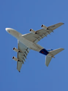
feelings and the available traces. At the back, close to the most rear door of the main deck, we installed a seat equipped with an intercom connected to the other crew members. A young flight test engineer was sat there, to give his opinion about his perception of comfort. Taking into account the number of roll manoeuvres we were performing on each flight, we had to hope that he would not become sick! It is true that a choice could have been made based on an analysis of the traces of several parameters of the motion at the various positions in the plane, but we considered that the opinion of a potential “passenger” was fundamental in order to make the final decision. Obviously, all the records of these parameters were used by the design office to make progress in the tuning of the flight controls laws. It is to be noted that, at the beginning of the program, we were concerned by a possible difference of comfort between the two decks. The first flights demonstrated that this was not an issue.
At the opportunity of your next flight on an A380, if you travel in business or economy class, I recommend that you book a “window seat”, close to the wing or at the back of the plane in order to see how the ailerons are working (in first class you
will not have this chance as you will be too far forward!). The effect is best observed just after take-off and during the early climb manoeuvres with the ailerons moving around their neutral position. You will see that when entering into a simple turn or for a unique roll correction, taking as a base the inner aileron, the one closest to you, the outer aileron will move simultaneously but with a smaller deflection. Then with a small time delay, the centre will join the inner. If several corrections are made by the pilot, in one direction then in another, taking into account the different deflections and the time delay, you will see the ailerons in totally different positions, up and down. The nickname “Valse Des Ailerons” is really well chosen and it is efficient.
The High Angle of Attack Protections at Low Mach Number
Section titled “The High Angle of Attack Protections at Low Mach Number”The tuning of the high angle protections, that prevent loss of control for all types of manoeuvres at low speed, has to be performed on all our new aircraft. The flight test techniques are well known by the test pilots.
We start with some decelerations with the engines at idle, slow manoeuvres at first and then faster, until achieving full back stick. At this stage, we have to check that we have some margin before reaching the stall. These tests are repeated in a stabilized turn and also with full thrust. If all the results are satisfactory, some rapid roll manoeuvres are carried out in one direction then in the other, while maintaining full back stick with various thrusts between idle and take-off power. The conclusion is the “avoidance manoeuvre” where the pilot rapidly puts the stick in the aft corner: a very
rapid turn will commence, the angle of attack will reach its maximum, and the engines will go to full thrust. This is exactly what a pilot would do to avoid another airplane or an obstacle. These tests must be performed for all slats and flaps positions. They must also be carried out for the extreme positions of the centre of gravity and with an aircraft light or heavy, as the reaction will be a function of all these parameters.
During the first flights of the A380, we performed an evaluation of these protections, but in a quasi-static way, with a slow deceleration. The reason was that we had to avoid approaching the stall because of potential high loads on the empennage. The engines were at idle and the target was to get a first idea of the tuning. During flight 7, at aft CG, we carried out some of these decelerations with satisfactory results.
The real tuning started when the slats and flaps deflections were frozen, end of July 2005, and immediately, we had a flight dedicated to these adjustments. We performed the tests at mid and aft CG, as the CG position could be adjusted in flight thanks to the water ballast system and when necessary some fuel transfer. During this flight, we avoided manoeuvres that were too dynamic, as we had still some doubts concerning the loads on some parts of the aircraft. The results were globally good, with the exception of the configurations 3 and Full, where the angle of attack was not properly stabilised when at full back stick, with therefore a risk of reaching the stall. So, for these configurations, we initially decided not to perform the turns with full back stick and maximum thrust.
The tuning continued with various standards of the PRIMs and, very quickly, in October 2005, the tuning of the protections was satisfactory. We proved that
at the Dubai Airshow where we performed the standard flight display, with high angle of attack manoeuvres, similar to the display carried out on all other Airbus types.
The Effect of Icing on the Tuning of Low Speed Protections
Section titled “The Effect of Icing on the Tuning of Low Speed Protections”However, the tuning of the protections at low speed was not complete. We had to ensure that with some ice on the leading edge of the wing, the protection is still doing its job properly. This is not a critical issue on big transport jets, as due to their rather high speed, it is far more difficult to accumulate a large amount of ice on the wing than on smaller and slower aircraft. But the certification regulations are the same for everybody, and obviously we had to comply.
Some tests are performed in real icing conditions, but it is not possible to accumulate on the leading edge an amount of ice giving a shape representative of the “worst case” required by the regulations. Therefore, the aerodynamicists compute for all flight phases, the ice shapes for the wings and the empennages for the most critical conditions. In order to avoid performing several series of tests with different shapes, only the most critical for all flight conditions is retained.
The ice shapes are then manufactured. They are made of polystyrene with some additional particles glued on in order to simulate the granularity of the ice. These shapes have a thickness of three inches, which is considered to be the maximum that an aircraft will keep on a leading edge. The regulations also consider that the de-icing system may fail. In this failure case, the relevant part of the wing is equipped with a smaller ice shape, as the crew will follow the procedures to leave the icing area, and therefore will accumulate a smaller
Safety
Section titled “Safety”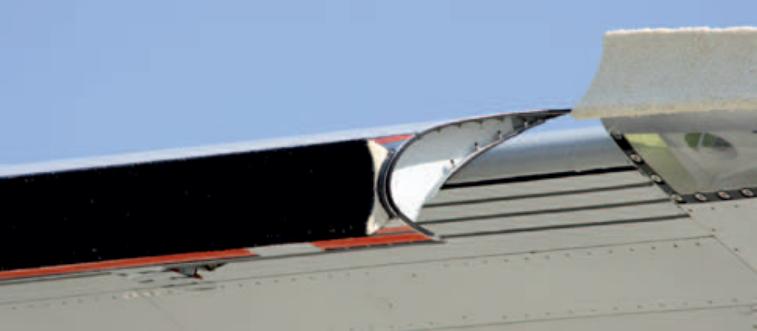
Figure 1 Polystyrene shapes simulating ice accretion
amount of ice. These ice shapes are then glued on the leading edge for the duration of the tests.
results were good. But there was a significant deterioration as the flaps were deflected. For the landing configuration, there was some loss of lift and a pitch up when approaching the stall. Our objective was to keep a safe aircraft, without degradation of the performance. Retaining more or less the same tuning for the angle of attack protections would have been an acceptable solution to save weight and simplify the systems. But, due to the pitch up, it appeared that the maximum angle of attack with the protections, in the landing configuration, would have to be reduced by two degrees, which was really too much. And therefore, we had to keep the de-icing system on slat 4. The flight test team was wrong and the aerodynamicists were right!
With the shapes in place, the tests start with an evaluation of the handling qualities and some stalls in order to check if the margin between the stall and the approach speed remains acceptable or not. If it appears that this margin has become insufficient, it is possible to recommend a small approach speed increase, such as 5 kts in case of severe icing or failure of the de-icing system. On the A380, none of the speeds or procedures needed to be changed in icing conditions.
The second step is to review the high angle of attack protections and adjust them, if necessary. The test techniques are identical to those used without ice shapes.
The tests continued with the tuning of angle of attack protections. The maximum angle of attack remained unchanged from configuration Clean to 2. Then in configurations 3 and landing, there was a reduction of 0.5 degree, without any consequence on the operation of the aircraft.
On the A380, on each wing, the slats are divided in seven sections and only slat 4, close to the outer engine, on the fuselage side, is deiced. Within the flight test team, we were convinced that this de-icing was not necessary. What could be the effect of a couple of inches of ice on such a huge leading edge? This design change could save around sixty kilograms of weight (about half a passenger !). Therefore we decided to start the tests with a configuration without the de-icing, which means with the three inches leading edge ice shapes on all the wings, including slats 4.
The tests were concluded with the validation of the failure case, a small ice shape on slat 4, with no other modification. Considering the previous tests with this slat fully iced, we were anticipating some degradation of the handling qualities. All we found was a slight difficulty to maintain the bank angle precisely with full back stick in the landing configuration. This was found acceptable due to the fact
The first flight with ice shapes was performed on June 26[th] 2006. As mentioned above, we started with the stalls. With flaps retracted, the
that this is a situation that will most probably never be found in the life of all A380s: the most severe icing conditions, associated with a failure case and a pilot maintaining the maximum angle of attack during several seconds. And anyway, it is perfectly safe as control is not lost.
In summary, these ice shape tests led only to a very small reduction of the maximum angle of attack in the flight controls protections in configurations 3 and Full.
The High Angle of Attack Protections at High Altitude
Section titled “The High Angle of Attack Protections at High Altitude”The aircraft must also be protected against the loss of control during decelerations and in turns at high and medium altitude with slats and flaps retracted. In these conditions, when the pilot pulls on the stick, without flight controls protections, the classic stall characteristics are not easy to detect as there is no visible stall nose drop compared to low altitude with the flaps extended. On the other hand, the buffeting appears progressively and, if the pilot insists and continues in the manoeuvre, eventually reaches a deterrent level. The angle of attack to get the deterrent level of buffet reduces with the Mach Number and therefore the tuning of the protections has to be done for all Mach Numbers.
For these tests, for each Mach Number, the crew chooses an altitude where he can perform tight turns, without imposing an excessive load factor. An exploration is performed without protection, in direct law, in order to identify the angle of attack of the appearance of the buffeting and of the deterrent buffet. These manoeuvres are difficult to perform, even for well trained test pilots, because, for the measurements, the Mach must be maintained precisely. It is controlled using the bank angle: as an example, decreasing
the bank angle in case of Mach increase (more nose up to decrease the rate of speed acceleration). Then, using these results, a first tuning of the protections is performed immediately and tested, the target is to be at the limiting level of the buffet when full back stick is reached. The tests start with turns where the load factor is very slowly increased. Then turns with fast increase of load factor are carried out. If, with the initial tuning, the buffeting is not found, the engineers will increase the maximum angle of attack by half a degree and re-perform the tests. On the other hand, if there is too much buffeting during all the manoeuvres, the maximum angle of attack must be reduced. As there is some scatter in the results of the manoeuvres, the ideal situation is to be just at the limit of the buffet. This implies having, sometimes no buffeting during smooth manoeuvres but reaching very briefly a strong buffet for aggressive pitch entries.
In summary, for each Mach Number, the tuning is carried out by progressive adjustment. It has to be repeated at various Mach Numbers in order to obtain the curve of maximum angle of attack versus Mach Number. These tests are first performed at forward CG. They must then be repeated at aft CG, which is usually done during the same flight. At aft CG, depending on the characteristics of the flight controls, it may be necessary to reduce very slightly the maximum angle of attack. If everything goes well, at the end of the flight, all the tunings are decided and will be transferred in the next standard of flight controls computers.
On the A380, we started these tests on August 31[st] 2005. It was flight 78 of aircraft MSN 1. The results were not fully satisfactory for several reasons. The development computers did not allow us the possibility to
insert the right tuning for Mach between 0.6 and 0.7. We also had difficulties in flying the aircraft in roll between Mach 0.80 and 0.84 and therefore, measurements were not very good. Finally, between Mach 0.80 and 0.89, the aircraft exhibited some pitch up (which means that it had a tendency to pitch up without pilot input) and was entering buffet very quickly.
These various problems were progressively solved. It is to be noted that the pitch up pheno-menon lead to a very delicate adjustment of the flight controls. When it appears, the flight controls law has to deflect the elevator down smoothly to oppose this immediate and strong motion pitch up effect. Finally, on May 10[th] 2006, a final revue of the adjustments was performed with very good results.
However, some more flights were needed to validate the behaviour of the protections with the airbrakes out. The issue was that the pitch up, if the pilot insists and continues in the manoeuvre, is a function of the deflection of the spoilers and as their extension is destroying the lift, it also reduces the pitch up. Therefore the “anti pitch up” function of the flight controls laws is adjusted according to the airbrakes position. On the A380, the first tests with airbrakes out demonstrated that the estimations obtained by models and wind tunnel were not correct. To cope with this situation, we performed some identification flights in direct law, with various airbrakes deflections, in order to define the automatic compensation to be introduced in the computers.
Part 3 will include the development of the high speeds protections, the BUSS (Back Up Speed Scale) and the BCM (Back Up Control Module).
Safety
Safety
Claude LELAIE
Section titled “Claude LELAIE”实验试飞员
A380:飞行控制系统研制
Section titled “A380:飞行控制系统研制”2005年7月27日,在图卢兹,我们遇到了强劲的南风,被称为“旺特风”(vent d’Autan),引发了强烈的湍流。这是首架A380的第51次飞行。我们进行了多次着陆,在此过程中发现横向飞控律需要重新调参:飞行员在驾驶杆上操作非常频繁,副翼运动幅度很大,在飞机后部产生了令人不适的侧向加速度。试飞工程师有多种调整控制律的手段:增益、阻尼……但没有一种能够解决这个问题。这种典型的研制缺陷必须得到纠正,但这并非易事。
10月中旬,新的PRIM飞控计算机交付使用,其中包含设计师办公室工程师们称为“VDA”或“副翼华尔兹”(Valse Des Ailerons)的新型副翼控制律。举例来说,当向左压杆时,左侧机翼上,内侧副翼立即向上偏转。外侧副翼同样向上偏转,但偏转量不同。最后,中央副翼要么最初向下偏转——与另外两个副翼反向——然后转为向上位置,要么在短暂延迟后从中立位置向上偏转。试飞工程师可以进行多项调整,例如内侧与外侧副翼之间的偏转比例,以及中央副翼的控制逻辑。这种奇特的运动学设计目的是“打破”某些机翼振荡,因为其中两个振荡具有非常接近的频率,在某些情况下可能相互耦合。查看机组可用的飞行控制页面时,很容易理解为什么副翼的这种奇特运动会得到“副翼华尔兹”这个昵称。类似的不同步偏转也应用于两个方向舵上,被称为“VDR”或“方向舵华尔兹”(Valse Des Rudders),这是一个典型的空客式“英法混合”缩写,因为“方向舵”在法语中并非标准词汇!舒适性的改善非常显著。然而,仍需要进行一些调参。
2006年1月,我们安装了新版本的计算机,对VDA控制律进行了改进。主要改进是降低了副翼的活动幅度。调整工作再次通过试飞进行。最终调参结果为:速度低于300节时,内侧副翼的偏转量是外侧副翼的2.5倍。中央副翼跟随内侧副翼运动,但有350毫秒的延迟。在高空由于马赫效应,还需要进行更多修改。
但我们还遇到了另一个问题:扰流板的调参。最初,只要发出横滚指令,扰流板就会立即偏转,这产生了抖振。2006年2月中旬,设计师办公室提出了新的设置方案以减少这种振动,将偏转角度限制在3°以内——只要飞行员没有强烈需求的话。没有这个技巧,我们的一位英国试飞员告诉我们,在进行标准转弯时他感觉像是被抖振“惩罚”了!此外,在最终调参中,当需要更高的机动性时,外侧扰流板的偏转幅度大于内侧扰流板,因为外侧扰流板产生的抖振更小。
对于所有这些舒适性评估非常重要的试飞,需要在飞机多个位置进行定性评判。在驾驶舱中,飞行员给出他们的感受,包括操控性和飞机前部的舒适性。试飞工程师坐在重心附近的位置,根据他们的主观感受和可用数据给出他们的判断。在后部,靠近主舱最后方的舱门,我们安装了一个配备内话的座椅。一位年轻的试飞工程师坐在那里,就他对舒适性的主观感受发表意见。考虑到每次飞行中我们进行的横滚机动数量,我们不得不希望他不要晕机!诚然,也可以根据飞机各位置的运动参数轨迹分析来做出选择,但我们认为潜在“乘客”的意见对于最终决策至关重要。显然,所有这些参数的记录都被设计师办公室用于改进飞控律的调参。值得注意的是,在项目初期,我们曾担心两个客舱层之间可能存在舒适性差异。首飞表明这并不是问题。
下次您乘坐A380出行时,如果您乘坐公务舱或经济舱,我建议您预订“靠窗座位”,靠近机翼或飞机后部,这样可以观察副翼的工作状态(一等舱您不会有这个机会,因为您会离得太靠前!)。最好的观察时机是刚起飞后和初始爬升机动阶段,此时副翼围绕中立位置运动。您会看到,当进入一个简单的转弯或进行单一的横滚修正时,以最靠近您的内侧副翼为基准,外侧副翼会同时偏转,但偏转量较小。然后,经过一小段延迟,中央副翼跟上内侧副翼。如果飞行员连续进行修正,先是一个方向然后是另一个方向,考虑到不同的偏转量和时间延迟,您会看到副翼处于完全不同的位置——有的向上,有的向下。“副翼华尔兹”这个昵称确实非常贴切,而且效果显著。
低马赫数下的大迎角保护
Section titled “低马赫数下的大迎角保护”针对低速飞行时所有类型机动中防止失去控制的迎角保护调校,必须在我们所有新机型上完成。飞行试验技术已为试飞员所熟知。
我们从发动机慢车状态下的减速开始,先进行缓慢机动,然后逐渐加快,直至达到全拉杆。此时,必须确认在接近失速之前仍有足够余量。这些测试在稳定盘旋中重复进行,并使用全推力状态。如果所有结果均令人满意,则在保持全拉杆的同时,以不同推力状态(从慢车到起飞功率)执行快速横滚机动,先从一个方向再从另一个方向。最后是”避让机动”,飞行员迅速将杆置于后角位置:飞机会开始一个非常快速的转弯,迎角将达到最大值,发动机将加至全推力。这正是飞行员为避开另一架飞机或障碍物时会做出的动作。这些测试必须在所有缝翼和襟翼位置下执行,还必须在重心前后极限位置以及飞机轻载和重载状态下进行,因为响应取决于所有这些参数。
在A380的首飞阶段,我们以准静态方式(缓慢减速)对这些保护进行了评估。原因是必须避免接近失速,因为潜在的尾翼载荷可能过大。发动机保持在慢车状态,目标是获得对调校效果的第一印象。在第七次飞行中,在后重心条件下,我们执行了若干次减速,结果令人满意。
真正的调校始于缝翼和襟翼偏转角度冻结后,即2005年7月底,随即我们专门安排了一次飞行进行这些调整。由于可利用水压舱系统在飞行中调节重心位置必要时进行燃油传输,我们在中重心和后重心状态下执行了测试。在这次飞行中,我们避免了过于动态的机动,因为对某些部位载荷仍存在一些疑虑。结果总体良好,但配置3和全构型状态下,在全拉杆时迎角未能适当稳定,存在到达失速的风险。因此,对于这些构型,我们最初决定不执行全拉杆加最大推力的转弯。
调校工作随着主计算机(PRIM)各种标准的迭代持续推进,并在2005年10月迅速完成了令人满意的保护调校。我们在迪拜航展上证明了这一点——当时执行了标准飞行表演,展示了高迎角机动,与在所有其他空客机型上进行的展示表演类似。
结冰对低速保护调校的影响
Section titled “结冰对低速保护调校的影响”然而,低速保护调校尚未完全。我们必须确保即使机翼前缘存在积冰,保护仍能正常发挥作用。在大型运输机上这不是关键问题,因为其相对较高的飞行速度使得在机翼上积累大量冰层比在较小较慢的飞机上困难得多。但认证规章对所有机型一视同仁,显然我们必须满足其要求。
部分测试在真实结冰条件下进行,但要在前缘积累达到规章要求的”最严重情况”代表性的冰形是不现实的。因此,气动专家计算了所有飞行阶段中最严苛条件下机翼和尾翼的冰形。为避免用不同冰形进行多轮测试,仅保留对所有飞行条件最关键的冰形。
然后制造冰形。冰形由聚苯乙烯制成,表面粘附额外颗粒以模拟冰的粗糙度。这些冰形厚度为三英寸,被认为是飞机前缘上会保留的最大厚度。规章还考虑了防冰系统可能失效的情况。在此失效情况下,机翼的相关部位配备较小的冰形,因为机组将遵循程序离开结冰区域,因此只会积累较少的冰。
图1 模拟冰积聚的聚苯乙烯形状
大量的冰。这些冰形随后被粘在测试期间的前缘上。
结果良好。但当襟翼偏转时,出现了明显的性能恶化。对于着陆构型,在接近失速时有一些升力损失和抬头。我们的目标是保持飞机安全,不降低性能。保持大致相同的迎角保护调校是一个可以接受的解决方案,可以节省重量和简化系统。但是,由于抬头问题,似乎在着陆构型下,带保护的最大迎角需要减少两度,这实在太多了。因此,我们必须保留4号缝翼的除冰系统。飞行测试团队判断有误,空气动力学家才是正确的!
安装冰形后,测试从评估操纵品质和进行一些失速测试开始,以检查失速和进近速度之间的裕度是否仍然可以接受。如果该裕度变得不足,可以建议小幅增加进近速度,例如在严重结冰或防冰系统故障时增加5节。在A380上,结冰条件下无需更改任何速度或程序。
第二步是审查大迎角保护,必要时进行调整。测试技术与未使用冰形时相同。
测试继续进行迎角保护的调校。从干净构型到构型2,最大迎角保持不变。然后在构型3和着陆构型中,减少了0.5度,对飞机运营没有任何影响。
在A380上,每侧机翼的缝翼分为七个部分,只有4号缝翼(靠近外侧发动机,在机身侧)装有除冰系统。飞行测试团队内部确信这个除冰是不必要的。在如此大的前缘上,几英寸的冰能有什么影响?这个设计变更可以节省约六十公斤的重量(约半个乘客的重量!)。因此,我们决定在没有除冰的情况下开始测试,即所有机翼(包括4号缝翼)上都有三英寸的前缘冰形。
测试以验证故障情况结束,即4号缝翼上有小冰形,其他没有任何修改。考虑到之前该缝翼完全结冰的测试,我们预期会出现一些操纵品质下降。我们发现的全部问题只是在着陆构型下使用全后拉杆时略微难以精确保持横滚角。这被认为是可接受的,因为这种情况在所有A380的使用寿命中很可能永远不会发生:在最严苛的结冰条件下,伴随故障情况,飞行员保持最大迎角数秒。而且无论如何,这是完全安全的,因为并未失去控制。
第一次带冰形的飞行于2006年6月26日进行。如上所述,我们从失速测试开始。在襟翼收上时,结果良好。但当襟翼偏转时,出现了明显的性能恶化。对于着陆构型,在接近失速时有一些升力损失和抬头。我们的目标是保持飞机安全,不降低性能。保持大致相同的迎角保护调校是一个可以接受的解决方案,可以节省重量和简化系统。但是,由于抬头问题,似乎在着陆构型下,带保护的最大迎角需要减少两度,这实在太多了。因此,我们必须保留4号缝翼的除冰系统。飞行测试团队判断有误,空气动力学家才是正确的!
总而言之,这些冰形测试仅导致构型3和全形态(Full)下飞行控制保护中最大迎角的极小减小。
高海拔大迎角保护
Section titled “高海拔大迎角保护”飞机在高空和中空收上缝翼和襟翼时,还必须在减速和转弯过程中防止失控。在这些条件下,当飞行员拉杆时,如果没有飞控保护,经典失速特性不容易被察觉,因为与低空放下襟翼相比,不会出现明显的失速低头。另一方面,抖振会逐渐出现,如果飞行员坚持继续此机动,最终会达到威慑水平。达到威慑水平抖振的迎角随马赫数增大而减小,因此保护功能的调校必须覆盖所有马赫数。
在这些测试中,针对每个马赫数,机组选择一个可以执行紧密转弯的高度,且不施加过大的载荷因数。需要在无保护的直接 law 状态下进行探索,以识别抖振出现时的迎角和威慑水平抖振的迎角。这些机动即使对训练有素的试飞员来说也很难执行,因为对于测量来说,马赫数必须被精确保持。马赫数通过坡度角来控制:例如,在马赫数增加时减小坡度角(需要更多抬头以降低加速率)。然后,利用这些结果,立即对保护功能进行首次调校并测试,目标是当达到全后拉杆时处于抖振的限制水平。测试从载荷因数非常缓慢增加的转弯开始,然后进行载荷因数快速增加的转弯。如果使用初始调校后未发现抖振,工程师将把最大迎角增加半度并重新执行测试。另一方面,如果在所有机动过程中出现过多抖振,则必须减小最大迎角。由于机动结果存在离散性,理想情况是恰好处于抖振限制边界。这意味着在柔和机动过程中有时不会出现抖振,但在快速俯仰输入时会产生短暂强烈的抖振。
总之,针对每个马赫数,调校通过渐进调整方式进行。需要在多个马赫数下重复,以获得最大迎角与马赫数的关系曲线。这些测试首先在重心靠前(forward CG)状态下进行。然后必须在重心靠后(aft CG)状态下重复,通常在同一飞行中完成。在重心靠后状态下,根据飞控特性,可能需要略微减小最大迎角。如果一切顺利,在飞行结束时,所有调校参数将被确定并转入飞控计算机的下一个标准版本。
在 A380 上,我们于 2005 年 8 月 31 日开始这些测试。这是 01 号机的第 78 次飞行。由于几个原因,结果并不完全令人满意。开发计算机不允许我们输入马赫数 0.6 至 0.7 之间的正确调校参数。我们在马赫数 0.80 至 0.84 之间飞行飞机横滚也存在困难,因此测量结果不太理想。此外,在马赫数 0.80 至 0.89 之间,飞机表现出一些抬头现象(这意味着它有无飞行员输入的抬头趋势),并且非常快速地进入抖振。
这些各种问题被逐步解决。值得注意的是,抬头现象导致飞控调整非常微妙。当抬头现象出现时,飞控 law 必须平滑地偏转升降舵向下,以抵消这种即时且强烈的抬头效应。最终,2006 年 5 月 10 日,对调整参数进行了最终审查,结果非常良好。
然而,还需要更多的飞行来验证放减速板时保护功能的表现。问题是,如果飞行员坚持继续此机动,抬头现象是扰流板偏转的函数,而扰流板的展开会破坏升力,因此也会减小抬头现象。因此,飞控 law 的“防抬头”功能需要根据减速板位置进行调整。在 A380 上,放减速板的首次测试表明,通过模型和风洞获得的估算结果并不正确。为了解决这一情况,我们使用不同的减速板偏转在直接 law 状态下执行了识别飞行,以确定需要引入计算机的自动补偿。
第三部分 将包括高速保护、BUSS(Back Up Speed Scale,备用速度刻度)和 BCM(Back Up Control Module,备用控制模块)的开发。
Safety